

BEIER · 北京第二机床厂有限公司 · Beijing
BEIER grinding: define the diameter, face and support together.
Compare MKS1320 and MKS1332 for external grinding. An end face leads to the separately identified 1620/1632 route. Then specify wheel dressing, part support and measurement as one process.
Original company, grinding tables and independent records reviewed 8 October 2026
Choose the supported grinding envelope, not bed swing alone
Beijing No.2 Machine Tool Works publishes external, internal, OD/end-face, compound and follow-up non-circular grinding, polishing and superfinishing equipment. Its MKS references below are external-grinding routes; a crankshaft, cam or combined bore/face job needs the appropriate process and machine configuration rather than a larger diameter figure alone.
Swipe the comparison sideways on a phone to read each complete column.
| Supported-part check | MKS1320 | MKS1332 |
|---|---|---|
| Maximum swing / grinding diameter | Ø220 / Ø200 mm | Ø360 / Ø320 mm |
| Centre-distance variants | 320 / 630 / 750 mm | 750 / 1000 / 1500 mm |
| Maximum mass between centres | 100 kg | 150 kg |
| Centre height | 160 mm | 180 mm |
| Headstock / tailstock centres | MT4 / MT4 | MT5 / MT5 |
| Workhead speed reference | 30–300 rpm, stepless | 30–300 rpm, stepless |
| Tailstock centre travel | 60 mm | 60 mm |
| Wheel-spindle motor reference | 7.5/11 kW pair; duty to confirm | 18.5 kW; duty to confirm |
| Machine mass by length variant | 4500 / 5500 / 6500 kg | 10,000 / 11,000 / 13,000 kg |
Stepped shaft with several journals
Send centre-hole condition, unsupported span, journal locations, shoulders and grinding allowance. Check support and wheel/guard approach for the complete part, including the drive arrangement and tailstock. Centre distance is not automatically the length of every surface that can be ground without interference.
Diameter with a critical shoulder or face
Show the datum relationship and required face runout/perpendicularity. Ask whether the cut uses an OD route, an angled wheel arrangement, a formed wheel or a different compound configuration. Do not infer an internal-grinding attachment or non-circular tracking function from an external-grinder family name.
The paired model pages separate external and end-face routes
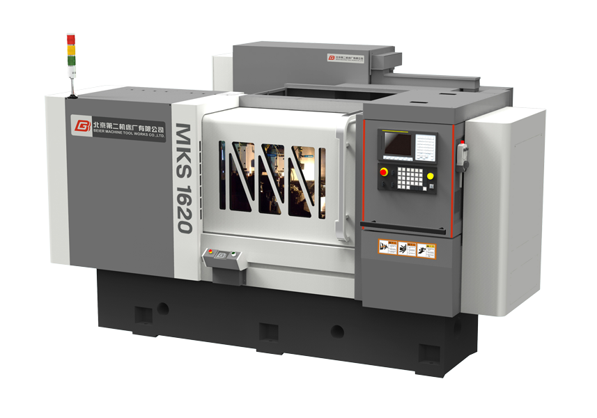
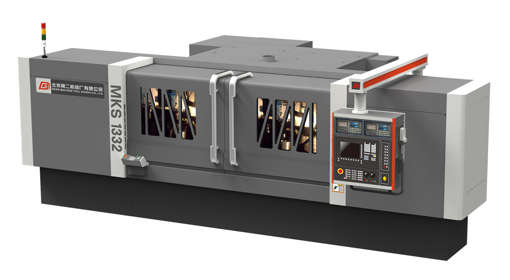
The published wheelhead-angle entries are 90° for MKS1320/1332 and 60° for their MKS1620/1632 end-face partners. Obtain the manufacturer's drawing showing the angle datum, wheel shape and access to the required shoulder. The H/G compact 1320/1620 variants have a separate table, including a 50 kg between-centres load; those figures are not the base MKS1320 specification.
Build the grinding process from wheel selection to gauge correction
Wheel and material condition
Define material, hardness, stock allowance, diameter and shoulder geometry. The base 1320 page lists Ø500 × 110 × 203.5 and Ø600 × 80 × 305 mm wheel references; 1332 lists Ø750 × 120 × 305 mm. These are source-listed configurations, not interchangeable wheel choices. The prose describes 60 m/s and CBN 80 m/s as special-order arrangements. Obtain the approved wheel, spindle speed, guard and coolant package for the selected build.
Profile and dressing
The base pages describe selectable diamond dressing arrangements behind the workhead with CNC dressing and compensation. A form, taper, groove or radius needs the wheel-profile drawing, dresser approach, dressing cycle and compensation rules. Include wheel wear and dressing time in the output target; a correctly shaped new wheel alone does not establish stable production.
Measurement and correction
The source describes active measurement and closed-loop grinding control. Confirm the supplied gauge, measured surfaces, allowable part geometry, calibration, correction limits and response to an out-of-range result. A controller command increment or in-process diameter reading is not a released-part roundness or geometry guarantee.
Use standard-testpiece figures as a starting reference
The original pages label their accuracy tables “standard testpiece.” For 1320/1620 they publish roundness 0.002 mm and diameter consistency 0.003 mm for the 320 variant or 0.005 mm for 630/750. For 1332/1632 they publish roundness 0.003 mm and diameter consistency 0.008 mm. Those are named source references, not an acceptance promise for an arbitrary long, thin or thermally sensitive part.
Match the surface and grinding method
The 1320/1620 page separates Ra 0.16 µm traverse, Ra 0.32 µm plunge and Ra 0.63 µm face-grinding references. The 1332/1632 page gives Ra 0.2, 0.4 and 0.63 µm respectively. Specify the relevant surface, wheel condition, coolant, measuring direction and inspection method; don't carry the best traverse finish into every plunge or end-face operation.
Agree the representative trial
Bring a workpiece with the intended material/heat treatment, centres, allowance and support. Record wheel/dresser/gauge, grinding and spark-out sequence, thermal conditions, dressing interval and the complete cycle. Inspect diameter, roundness, longitudinal consistency and shoulder/face relationships after release as required by the drawing. Define sampling and repeat tests after installation before accepting a production result.
Confirm the supplier, process support and document package
The company's current introduction identifies 北京第二机床厂有限公司 and its BEIER brand, with research, production and sales of grinding and superfinishing equipment. A 24 September 2025 Beijing government report names the company and a separate B2-GK3012X500 compound grinder. That dated record supports the company identity and reported activity; its compound-machine claims are not transferred to the MKS references.
The standards platform lists the company as a drafting participant for GB/T 23571-2009, concerning machine-tool technical documentation, with continued validity recorded at its July 2025 review. This is drafting participation, not certification of a delivered grinder. Agree the current technical documents, drawings, acceptance reference and control/gauge configuration in the contract.
The manufacturer describes presale machine selection and process-planning support. Its warranty-service page publishes response and site-arrival timings without establishing overseas coverage. Specify commissioning, gauge calibration, grinding-process training, parts and destination support separately. Obtain current foundation and lifting drawings, oil/coolant utilities, temperature conditions and all service-access space for the selected length variant; an old layout sketch is not a site-engineering instruction.
Send the journal, shoulder and inspection requirements
Attach material/hardness, blank and finished drawing, centre-hole and datum details, journals/faces, allowance, part mass, unsupported spans, roundness and finish requirements, wheel/dressing preferences, gauge/sampling method, complete output target and destination. Identify base 1320, 1332 or a separate end-face/compound route, then agree the current configuration and representative trial.
BEIER RFQ ↗