

苏州伟扬精机有限公司 · Chevalier, Changshu
Start with the part: small-part turning or an 850 VMC-L machining setup
Suzhou Weiyang's two references serve different drawings. Check the real turning envelope for FCL-140; check fixture height, tool reach and spindle configuration for 850 VMC-L.
Official pages, specification tabs and original catalogues reviewed 8 October 2026
Which features set the first operation?
Bar, shaft or chuck blank
Use FCL-140 as the turning reference when OD, bore, face and turned profiles define the part. Decide bar-fed versus individually loaded stock, then check the grip, unsupported length and whether tailstock support leaves access to the required faces.
Review FCL-140 ↗Prismatic part or mould
Use 850 VMC-L as the milling/drilling reference for a fixture on a rectangular table. Plan the datum, clamp positions, tool lengths and inaccessible faces before treating three-axis travel as a complete part envelope.
Review 850 VMC-L ↗A component that combines turned datums with off-axis holes or milled faces may need an agreed transfer and second setup. FCL-140's ordinary hydraulic turret is not the FCL-200MC live-tool package described elsewhere in the catalogue.
FCL-140: distinguish swing, cutting diameter and bar passage
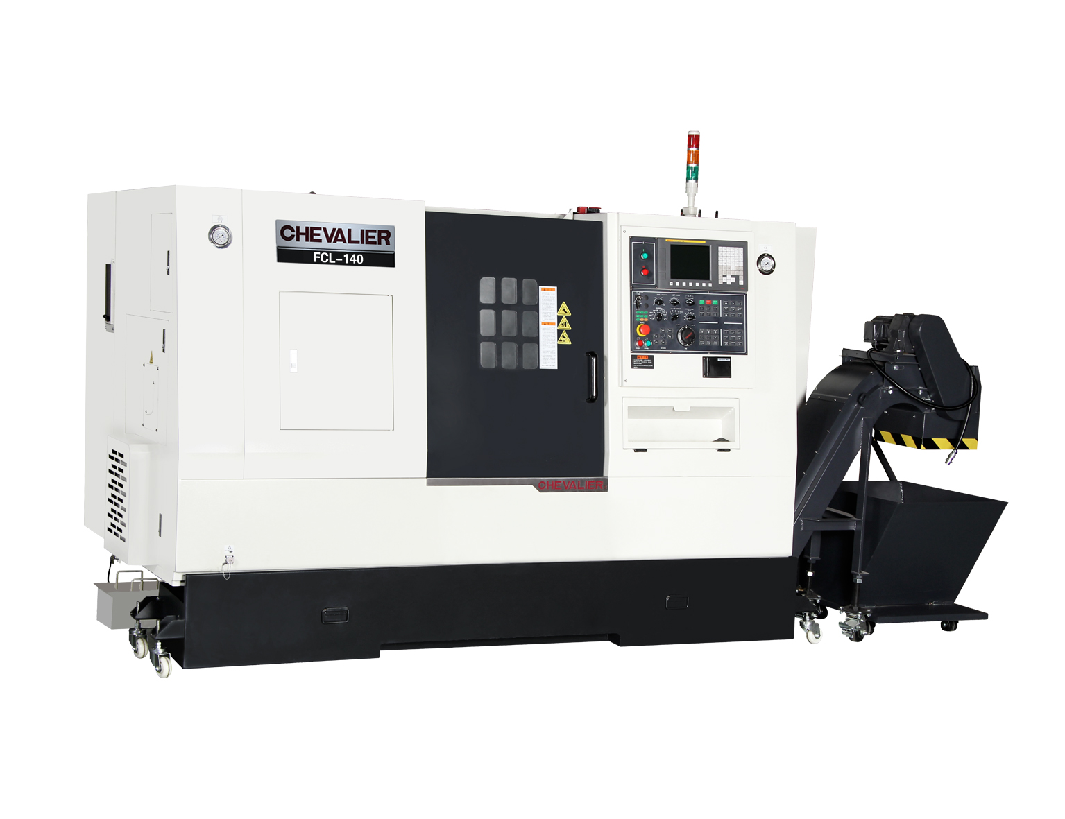
- 470 mm swing ≠ 470 mm cut
- The FCL-140 catalogue column gives 470 mm bed swing, 284 mm saddle swing and 260 mm maximum machining diameter. Use the machining figure as the initial cut-envelope check, then prove jaw, holder, turret and tailstock clearance on the actual setup.
- 57 mm bore ≠ 57 mm bar
- The same column gives a 57 mm spindle through-hole but a 45 mm maximum bar passage, with an A2-5 nose and six-inch chuck. Specify the stock diameter, liner, collet/chuck and feeder interface together.
- 290 mm machining length
- The catalogue lists 290 mm maximum machining length and 397 mm between centres. Those dimensions do not remove the space taken by jaws, grip allowance or the tailstock centre. Submit the blank length, gripped length and end-face access.
The page describes a 6000 rpm spindle, a ten-tool hydraulic cam turret and an MT4 hydraulic tailstock. Gang tooling is a separately described option; the FCL-140A column is a different tooling arrangement. Choose the installed tool package from the actual sequence, rather than combining both columns or promising the catalogue's claimed productivity increase.
850 VMC-L: fit the fixture and tool stack inside the travel
- Worktable
- 1000 × 510 mm; published maximum table load 500 kg.
- X / Y / Z travel
- 850 / 530 / 510 mm.
- Spindle nose to table
- 150–660 mm in the 850 catalogue column.
- Tool system
- BT40 reference, 24-position arm-type ATC; catalogue tool envelope Ø80 mm and 300 mm length.
Count the fixture, part and any rotary unit in the table load. Lay out clamp reach and the furthest toolpath over the 1000 × 510 mm table; the full table is not covered by 1000 mm of X travel.
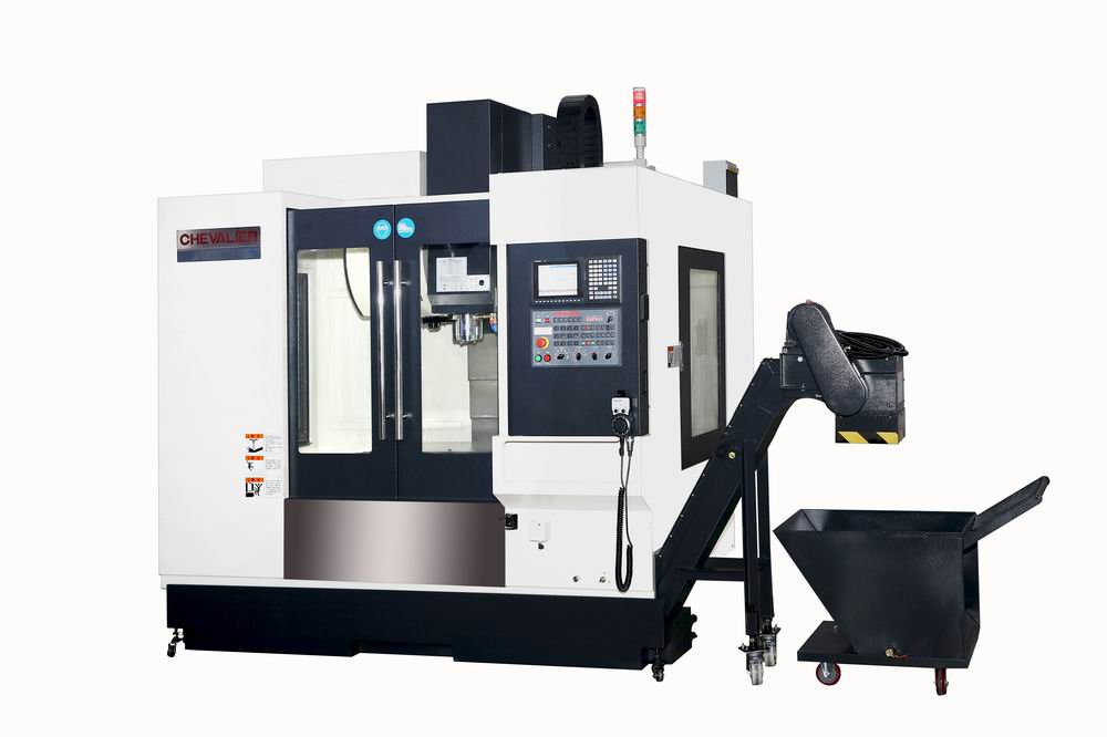
Stack fixture height, part height and the tool/holder extension against the 150–660 mm nose-to-table range. Check the lowest cut, longest drill, tallest clamp and tool-change clearance. If a fourth axis is required, request its swing, support, added mass and control/postprocessor package; it is an option in the catalogue.
Freeze the machine package before comparing quotations
Spindle and tooling
The 850 webpage specifies a belt-driven 10,000 rpm spindle as standard, with 8000/12,000 rpm alternatives. Quote the selected speed/drive, usable torque at the cut and toolholder balance requirement. The larger VMC-L models have different standard entries. A family maximum speed is not the supplied 850 specification.
Measurement and coolant
The VMC catalogue separates tool-length measurement, workpiece measurement, through-spindle coolant, fourth-axis equipment and a larger magazine from the standard package. State which items are supplied, their interfaces and commissioning scope. A probe-equipped machine still needs a datum strategy, calibration and an inspection method for the accepted part.
Loading and chip handling
For FCL-140, agree bar feed, collection and door/interface options if unattended loading is needed. The page describes side or rear chip discharge and a front-access coolant tank. Draw the actual conveyor, tank removal, stock loading and service access in the installed footprint; the machine outline alone does not describe the required working area.
Prove the cycle that the operator will actually run
Turning: retain the real grip and support
Trial the intended bar/chuck blank, jaw or collet, tailstock condition and tool sequence. Include part-off or unload, the next-stock advance and a restart where applicable. Inspect the specified diameter, roundness, face runout, bore and length using the drawing's datums after release. Keep the grip/support parameters with the results.
Milling: include the tallest fixture and longest tool
Run the datum setup, tool changes, deepest hole/pocket and any second setup. Check reachable surfaces and collisions before cutting. Measure the relationship between features after unclamping, and include loading, probing, chip clearing and tool replacement in cycle evaluation.
Separate machine checks from part acceptance
The VMC webpage cites JIS positioning/repeatability figures, while its linked catalogue uses VDI 3441 entries with different numerical limits. Do not combine those methods into a tighter advertised result. Agree the actual machine inspection standard, travel, temperature and compensation state; separately define the trial-part size, geometry and finish requirements.
Ask for the installed tool/chuck list, electrical and lubrication documents, control and compensation backups, machine inspection record and agreed part-trial report. Repeat the relevant tool or setup change rather than accepting one specially prepared first piece.
Confirm the Suzhou supply and destination-service parties
The official company page identifies 苏州伟扬精机有限公司 in Changshu, Jiangsu. Its navigation and catalogue cover turning, machining centres and grinding equipment, and link to the wider Chevalier business. That does not establish that every global group machine is built, stocked or supported by this entity.
For the quotation, name the contracting entity, actual manufacturing/configuration location, installation provider, training and warranty/service party at the destination. Confirm which control version and regional components will be delivered and who supplies the commissioning records and replacement parts.
Send the blank, datums and installed package
Include the drawing and material; bar/chuck blank with grip and support, or fixture/part/tool-height stack; dimensions and feature relationships; batch and loading sequence; spindle, turret/ATC and coolant options; control/postprocessor needs; installation layout and destination; machine inspection and released-part trial requirements.
Send Chevalier RFQ ↗