

Jinan No.2 Machine Tool Group · Jinan, Shandong
JIER: plan access around the heavy part.
Compare moving-beam gantry work with floor-type boring and milling. Define the loaded envelope, head reach and foundation before choosing a series.
Choose the working layout ↓JIER RFQ ↗
Original series pages dated October/November 2020 · reviewed 8 October 2026
Can the part pass the bridge, or should the spindle approach it?
JIER manufactures metal-forming equipment and large metal-cutting machinery, with automation and related equipment in its wider catalogue. The two reviewed cutting series address large housings, plates and frames through different layouts. For a bulky setup, start with the actual fixture and access to each face; selecting only by spindle power can leave an unreachable bore or an impractical loading operation.
| Process question | XK21 moving-beam gantry | TK/TH69 floor-type boring / machining centre |
|---|---|---|
| Layout to investigate | Large plate, frame or housing inside the gantry opening; beam/ram and attachment-head access | Heavy housing with floor-plate or rotary-table arrangement; column, spindle box, ram and boring-bar reach |
| Published access references | Passage width 2600–6600 mm; height 2000–6000 mm | X travel 6000 + n × 1000 mm; Y 3000–8000 mm |
| Workholding reference | Table width 2000–6000 mm; listed load 5–25 tonnes per metre | Rotary table 2500 × 2500 to 5000 × 5000 mm; 30–160 tonne load range |
| Extension to review | W beam travel 1500–4000 mm; ram 950–2000 mm | W boring-bar travel 1200/1600/1800 mm; Z ram 1200/1600/2000 mm |
| First drawing to request | Loaded gantry clearance and head/holder envelope for every face | Floor/rotary layout, complete sweep and reach at actual bar/ram extension |
Swipe the table on a phone. These are series ranges from dated model material, not a single build whose values can all be selected at their maximum. Load per metre is not total table capacity; an offered rotary table also needs its own eccentric-load and overturning-moment conditions.
XK21: leave room for the attachment head and the tallest clamp.
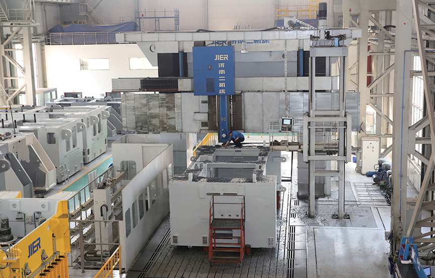
Opening versus usable cutting space
The table-width range is 2000–6000 mm and the published length expression is L = 2000 + n × 1000 mm. Specify the selected table, travel and gantry opening together. The 2600–6600 mm passage width and 2000–6000 mm height do not guarantee cutting reach with a tall fixture, angle head or long holder.
The page describes a moving beam, ram-type boring/milling and attachment heads, plus an electrohydraulic proportional dynamic-balance compensation system for W. Ask for each face’s head angle, tool extension, safe approach and head-change position. Compensation is a described mechanism, not a finished-part test result.
Load and cutting conditions
The listed 5–25 tonnes/m load range needs the selected table’s distribution, point-load and fixture conditions. Request a load map and complete working-envelope drawing. Beam W travel and ram travel are separate: extending either can alter the practical stiffness and access of the proposed cut.
Spindle power 22–110 kW and maximum speed 1200–4000 rpm are series ranges. Obtain the delivered speed/torque and duty curves, spindle/head interfaces and controller. The source’s rapid-motion line has ambiguous X/Y typography; settle the selected build sheet rather than deriving a cycle from that line.
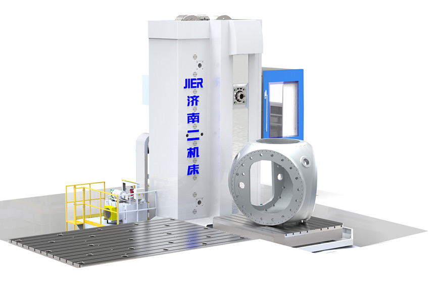
TK/TH69: work from the bore axis back to the support and floor.
The floor-type series lists boring-bar diameters 160/200/260/320 mm, spindle power 58–135 kW and maximum speed 1000–2000 rpm. Select those within an actual build; a diameter option is not the bore size it can finish at every extension or a guarantee that all power/speed maxima coexist.
The page describes closed hydrostatic guides and a rectangular ram supported within an enclosed cast-iron spindle box, with ram-deflection, spindle-box-offset and boring-bar compensation measures. Review the tool, head, bar and ram projection needed for the deepest bore. A larger bar does not replace a cutting trial at the intended unsupported length.
The rotary-table range is 2500 × 2500 to 5000 × 5000 mm with 30–160 tonnes listed load. A heavy housing’s centre of gravity, swept corners and clamp access can govern selection. Agree the selected table’s load distribution, overturning moment and indexing/clamping conditions, together with floor plates and the machine-column travel.
The source identifies JIER S-series software functions such as fault warning and wire-rope life monitoring. Confirm the control version, included functions, maintenance procedures and applicable lifting/safety systems for the delivered build; software descriptions are not a safety certification or a substitute for guarding.
Price the installation as a production project.
Foundation and environment
Ask for foundation loads, soil/floor assumptions, anchoring, levelling, settling and temperature requirements. Confirm utilities, hydraulic/cooling arrangements, chip collection and drainage using the delivered layout. A catalogue travel range does not provide a foundation design.
Lifting and access
Map the heaviest component and complete loaded fixture against crane capacity, lifting points, sling clearance and loading route. Include gantry passage, platform/door access, rotary sweep and safe head changes. Do not infer crane requirements from the nominal machine table load.
Commissioning responsibility
Separate building/foundation, unloading, assembly, geometry checks, controls and part-process commissioning. Agree destination labour, tools, schedule, acceptance documents and who resolves a discrepancy. The manufacturer’s service description explicitly makes installation/commissioning subject to contract or agreement.
Accept the critical bore and face relationship at the required reach.
For XK21, trial the tallest loaded setup and the face requiring an attachment head or greatest ram extension. For TK/TH69, trial the deepest bore at the quoted bar/ram projection and the datum relation after the planned rotary index or re-clamping. Use the offered tools, heads, control and representative material.
Geometry and thermal condition
Agree warm-up, ambient conditions, measurement method and full working-zone geometry checks. Inspect the released part, not only a short-axis movement. Record how compensation is set, backed up and verified after levelling or service.
Productive time and recovery
Separate cutting, head/tool change, loading, indexing, inspection and operator intervention. Include chip removal and a controlled-stop restart. Maximum power, rapid speed or a heavy-duty description alone cannot establish an accepted cycle.
Request the selected serial-machine and sample records. Neither series page supplies the tolerance of your housing, the stability of your foundation or a guaranteed result at every listed range extreme.
Separate manufacturing capability from the machine in the quotation.
The official profile identifies 济南二机床集团有限公司 and its metal-forming, cutting and automation businesses. Its manufacturing-capability page describes heavy-part, rotary-part, gear and precision-component machining. Those are workshop/service descriptions; their component machining capacities or accuracy claims are not assigned to XK21 or TK/TH69.
An August 2018 Ministry of Science and Technology notice names the company as leader of an accepted large servo press-line research project. That provides dated external corroboration of the entity and that project; it does not certify the two cutting series or establish present delivery performance.
The published service scope distinguishes contract-based commissioning and manufacturing-quality handling within the guarantee period from spares, maintenance, overhaul, modification and relocation afterwards. Confirm the selling/manufacturing entity, series revision, acceptance specification, destination support and heavy-component spares through the quotation. Do not convert a domestic service-centre list into an overseas response-time promise.
Send the loaded envelope, not just the part drawing.
Include part material/blank, dimensions and mass, fixture/centre of gravity, critical bores and face relationships, all required head approaches, bar/ram reach, rotary sweep and batch mix. Add destination foundation/environment, crane/loading route and utilities.
Request the selected series configuration, full layout/load map, head/tool list, foundation responsibilities, trial/inspection plan and destination commissioning scope through CNCVerified.
Prepare a JIER RFQ ↗