

Nanjing Tiantian · Sheet-metal equipment · Lishui
Define the sheet job before the laser package.
Compare three HTD-T1 bed formats, then qualify loading, the material-specific cutting recipe and released-part quality.
Current company and HTD-T1 source material reviewed 8 October 2026
Fit the actual sheet and nest.
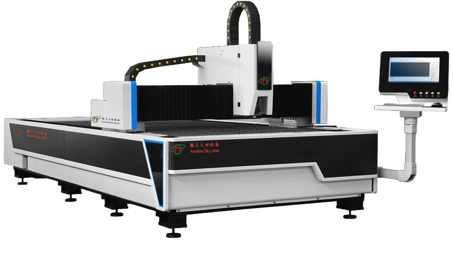
HTD-T1 is presented as a single-platform gantry fiber-laser sheet-cutting series. Its shared table lists six formats; the three retained model references below represent 3 × 1.5 m, 4 × 2 m and 6 × 2.5 m sheet areas.
Start from the purchased sheet sizes, margins, clamp/support zones, part mix and remnant strategy. A nominal format does not establish usable nesting boundaries, cutting thickness or a complete production cycle.
| Model | Working area (mm) | X / Y / Z travel (mm) |
|---|---|---|
| HTD-T1-3015 | 3000 × 1500 | 1505 / 3005 / 150 |
| HTD-T1-4020 | 4000 × 2000 | 2010 / 4010 / 150 |
| HTD-T1-6025 | 6000 × 2500 | 2510 / 6010 / 150 |
X/Y ordering follows the original Chinese table. These are sheet-area and travel entries, not tube capacities. On a narrow screen, swipe the comparison sideways.
A larger bed changes loading and removal too.
For 3015, check whether your regular sheets fit the actual support and margin requirements. For 4020, review the wider sheet grip and unloading route. For 6025, define how a long, wide sheet is supported, aligned and accessed over the whole nest, and how finished parts and remnants leave the bed.
The current shared table has a positioning figure in its workbench-load row and kilogram values in its maximum-speed row. Those entries do not provide a reliable supported-sheet mass or running-speed specification. Request a corrected signed row instead of guessing how misplaced values should be shifted.
Include actual sheet mass, lifting or loading method, support/slat arrangement, flatness, narrow parts and retention strategy. Test loading and part removal without damaging datums or edges, and account for changeovers and sorting in batch time.
Put the source, head and control on one quotation.
The family description names IPG or Raycus source alternatives, an autofocus-head description and CypCut in its control row. It does not identify one supplied source/head/controller revision for each retained format. Request the actual components, power rating, chiller, consumables, software functions and service responsibility together.
The web table's “1000W–200000W” power range is not used here as a confirmed available package. It also gives a 4700 mm overall length for a model with a 6000 mm working length. Those inconsistencies require a corrected configuration and installed-layout drawing; they are not silently rewritten into plausible figures.
State material grade, thickness, surface condition and edge requirements. Agree assist gas, nozzle, focus, pressure and piercing/cutting conditions in the sample record. The optical source's characteristics do not eliminate the need for cutting gas, cooling, extraction or protective arrangements for the complete system.
Accept the finished parts, not just the motion figures.
Choose a demanding nest
Include the actual material and the smallest holes, slots, corners, long edges and distortion-sensitive parts you expect to produce. Specify required geometry, edge condition, dross/burr limits and allowable rework.
Record the supplied process
Identify source/head/control revisions, material condition, supports, nozzle, gas, focus and cutting/piercing recipe. Include lead-ins, feature order and part retention where they affect the result.
Inspect after removal
Measure released parts against agreed datums after the defined cooling/handling condition. The page's ±0.05 mm positioning and ±0.03 mm repeat-positioning figures are machine-motion data, not guaranteed cut-part tolerances. Its minimum-line-width claim is not proof of acceptable holes or kerf for every material.
Time the complete batch
Record loading, aligning, piercing/cutting, unloading, sorting, consumable changes and normal interventions. Separate first-good-part time, repeat cycle and rework; do not turn a straight-line motion maximum into cutting throughput.
Plan the complete installed system.
Obtain an occupied-layout drawing for the actual build, including source/chiller, extraction, gas supply, maintenance zones and incoming/outgoing sheet routes. Confirm electrical supply, ground connection, cooling conditions and destination installation responsibilities.
The family is presented as a single-platform configuration. Its appearance does not prove the guarding, access control or optical protection needed for the delivered laser package. Have the responsible installation team review the supplied safety and integration documents and the actual operating arrangement.
Assign commissioning, operator training, fault recovery, remote/control support and consumable/spares responsibility. Confirm what is included before comparing total installed scope and costs.
Keep the company and wider equipment scope distinct.
The current company page identifies 南京天田机床制造有限公司 in Mingjue, Lishui, Nanjing. It describes shearing, bending, punching, rolling and related tooling, including HT11/HT12Y/HT12K shears, HT67Y/HT67K press brakes, HT21/HT23T presses and HTW11/HTW12/HTW11S rolls. These are separate product scopes from the retained HTD-T1 sheet-laser references.
This record uses that Nanjing company identity. It does not establish an affiliation with Japan's AMADA group or independently certify company registration, capacity or these machines. Confirm the legal seller, actual builder and supplied-model documents with the quotation.
The model-marked HTD-T1 photos presently carry contact watermarks and are withheld. The clean series illustration above remains a layout illustration. Obtain a matching model-marked photograph and corrected revision sheet before accepting the delivered configuration.
Send the sheet mix and the sample acceptance requirements.
Include material grades/thicknesses, sheet formats, a representative nest, geometry and edge limits, batch mix and downstream bending/forming needs. Add handling, available utilities and destination.
Name the proposed HTD-T1 format. Request corrected load, power and installed-layout data, an exact model-marked image, a matched component schedule and a released-part trial with full batch-time boundaries.
Prepare a Tiantian RFQ ↗