

Qiqihar Heavy CNC Equipment Co., Ltd. · Qiqihar, Heilongjiang
A heavy shaft needs a support plan.
Compare Qiqihar’s horizontal turning routes with the real workpiece, support positions and cutting task—not a combined set of catalogue maxima.
Compare the bed arrangements ↓Heavy turning RFQ ↗
Official series pages/tables and August 2026 issuer-report sections reviewed 8 October 2026
First choose how the workpiece and tools are supported.
The current horizontal-lathe directory distinguishes HTI, HTII/IIP and HTIII. The useful difference is the bed and support arrangement for shaft, disc and rotor work. A turning diameter does not establish the weight, support spacing, machining length or attachment clearance of the selected build.
| Series | Published arrangement | Before choosing a build |
|---|---|---|
| HTI | X/Z double-chevron guideways; separate tailstock guideway; optional rests and boring/grinding accessories | Loaded shaft, tailstock/rest locations and usable tool approach |
| HTII / HTIIP | HTII four-guideway bed; HTIIP three-guideway bed; different published load/diameter ranges | Roughing versus compound work, carriage configuration and the exact load version |
| HTIII | Separate tool/workpiece beds, hydrostatic X/Z guideways and selectable head combinations | Support reactions, hydrostatic services, working heads and the accepted process |
Swipe on a phone. Grinding/milling/boring accessories are offered choices, not standard simultaneous functions on every lathe.
HTII’s page describes a 1,250–2,000 mm machining-diameter range with 20–40 t load, and HTIIP a 1,600–2,500 mm range with 32–80 t load. These are series ranges. Do not assemble their largest diameter, length and weight into one assumed machine; ask for the complete model suffix, bed length and load-bearing arrangement.
Read the HTI table as alternatives, not one specification.
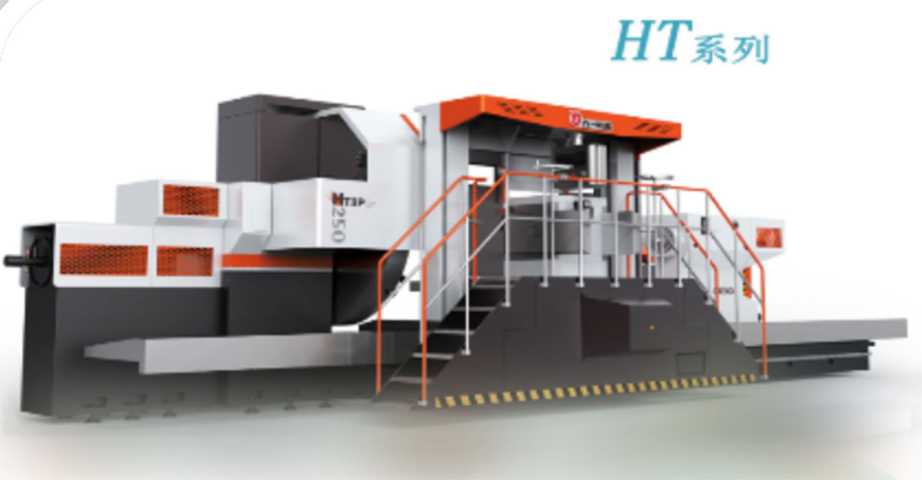
The HTI source table separates HTI100, HTI125, HTI140 and HTI160: maximum swing diameters 1,000, 1,250, 1,400 and 1,600 mm. It lists a maximum workpiece length of 18,000 mm for these columns. The weight entries are 6 t, 6/14 t, 6/14 t and 14 t respectively.
The slash entries do not explain a supplied support/build condition. Settle which load version applies, how the workpiece is carried and the offered length. “Maximum swing” is not an uninterrupted cutting diameter at every carriage, rest or fixture position.
HTIII’s tables similarly contain multiple weight values and parenthesised entries. They are not additive capacities. Request the exact headstock, tailstock, rest and bed arrangement for your mass distribution, overhang and process. The separate showcase machine’s 6,300 mm diameter and 400 t headline are not specifications for HTI or HL2540L.
The old HL2540L directory URL is retained. The current reviewed catalogue does not establish that exact designation’s dimensions, capacity or photograph. Supply an existing nameplate/build document for a service enquiry, or request the current offered model for a new machine; no HT-series values have been assigned to that old record.
Draw the load path and the tools on the same plan.
Headstock → shaft → tailstock/rests
Provide blank material, total mass, length, steps/diameters, centres and centre of gravity. Mark chuck/faceplate engagement, tailstock centre and each proposed steady rest. Ask the builder to qualify the support reactions and speed limits for that arrangement, including loading and intermediate setups.
Carriage → tool → feature
Mark cuts, groove access, bore depth and tool overhang with the supports present. A large swing can coexist with a blocked tool approach. For the published milling, grinding or boring accessories, agree positioning, locking, tool reach, coolant/extraction and the delivered control functions.
Ask how support pressure/alignment is set and recorded during the trial. Part straightness and concentricity depend on the real blank and support setup; a manufacturer’s guideway or bearing description is not a guarantee of released-part geometry. Keep roughing, finishing and inspection conditions explicit.
For a large lathe, site preparation is part of acceptance.
Before the machine arrives
Obtain the exact foundation/installation drawing, machine and separate-unit weights, anchor/interface requirements, utilities and maintenance access. Check delivery route and lifting plan against the actual plant. A catalogue working length is not the installed footprint.
Before the first cutting trial
Agree alignment and environmental conditions, workholding/support procedure, supplied heads, tooling and control program. Include the important heavy roughing and difficult-access finishing features from the representative workpiece.
Before sign-off
Measure the agreed datums, straightness, concentricity, sizes and surface requirements under documented support/thermal conditions. State whether the part is inspected in situ or after release and which result governs acceptance. Record the complete cycle and operator interventions; add attachment-change and service recovery demonstrations where supplied.
Confirm the builder behind the Qiqihar No.1 brand.
The official material presents Qiqihar Heavy CNC Equipment Co., Ltd. and a manufacturing history beginning in 1950, including later corporate changes. The August 2026 HuiZhou Intelligence interim report identifies 齐重数控 as 齐重数控装备股份有限公司 and describes its focus on heavy vertical and horizontal lathes, with other CNC product categories. Historical factory age is separate from the current contracting entity.
The current official directory also covers vertical turning, hobbing, gantry milling and other precision equipment. This page concentrates on horizontal support choices; those other processes need their own current model and tool/fixture qualification. A named manufacturing group or history does not establish a specific machine certification.
For a new build, identify the legal seller, manufacturing plant and team responsible for foundation guidance, installation, control/attachment integration and spares. Settle a regional service arrangement and response obligations in the quotation, rather than treating a branch name or published application industry as a delivery guarantee.
Send the shaft and the support drawing.
Include material/blank condition, mass and centre of gravity, overall and stepped dimensions, chuck/centre/rest positions, critical cuts/bores/grooves and released-part inspection requirements.
Add the desired turning/milling/grinding/boring scope, head and tool access, batch mix, current nameplate if relevant, site/handling constraints and destination. Ask for one qualified model/build, a foundation plan and a representative acceptance trial.
Prepare a Qiqihar RFQ ↗