

SW / Schwäbische Werkzeugmaschinen
Suzhou regional operations
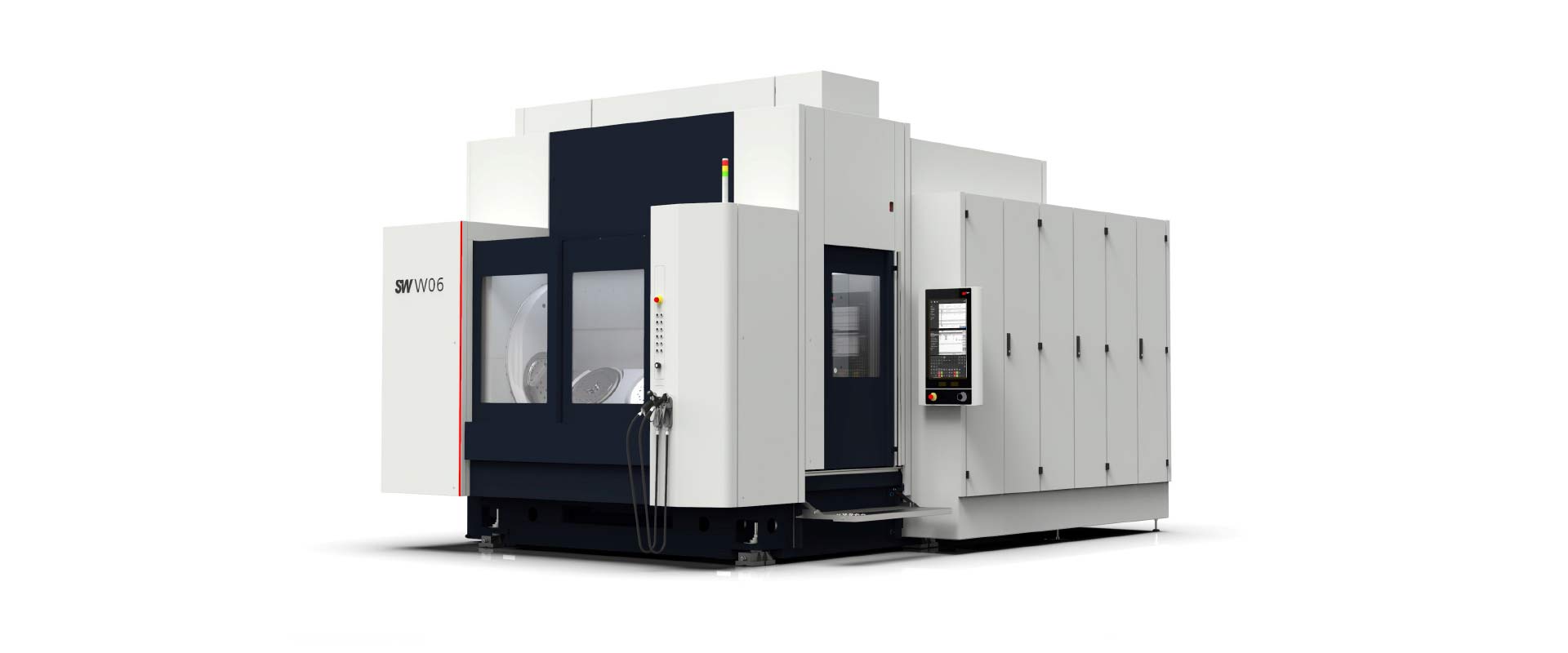
SW BA W06: choose spindle lanes around the part and the production cell
One, two or four spindles change the workspace available to each part, the fixture pitch and the loading system. Compare accepted output from the whole cell, including tool changes and rejects.
Group model page, technical data and China location reviewed 8 October 2026
Start with workspace per spindle, not the enclosure size
On a small screen, swipe the comparison horizontally.
| Selection check | BA W06-11 | BA W06-22 | BA W06-42 |
|---|---|---|---|
| Machining spindles | 1 | 2 | 4 |
| Per-spindle X / Y / Z | 1150 / 630 / 510 mm | 600 / 630 / 510 mm | 300 / 600 / 500 mm |
| Spindle pitch | No paired pitch | 600 mm fixed; variable pitch is optional | 300 mm |
| Workholding boundary | Clamping bridge reference up to Ø1000 × 1505 mm | Fixture-plate envelope up to Ø675 × 1430 mm; two 600 kg carrier loads | Fixture-plate envelope up to Ø675 × 1430 mm; two 600 kg carrier loads |
| HSK-A63 magazine baseline | 84 positions | 2 × 42 positions | 4 × 21 positions |
| Buyer decision | Retain the wider single-part X workspace | Prove two corresponding nests and a balanced loading route | Prove four accessible, repeatable nests within the smaller lane |
| Existing model reference | Open -11 ↗ | Open -22 ↗ | Open -42 ↗ |
These are the linked technical sheet's configuration references. Optional rotary satellites, alternative spindle interfaces and magazine extensions require project planning. The additional Y tool-change positions are not extra cutting workspace.
Design the fixture for every spindle lane
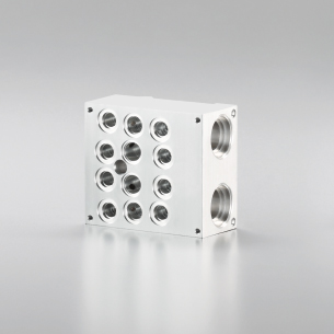
For a housing or manifold with several bores and faces, map the datum, tools and clamping access before choosing the number of spindles. More simultaneous parts do not help if a clamp, tall boss or long tool obstructs the matching operation in one lane.
BA W06-22 lists a fixed 600 mm spindle distance, with 590–651 mm variable distance as an option in the technical sheet. BA W06-42 lists 300 mm pitch. Provide a fixture layout showing all nests, locating surfaces, clamp actuators and the complete rotated sweep.
- Carrier load is not per-part payload
- The -22 and -42 sheet entries list two carrier loads of 600 kg. Include plate, fixture, clamps and every blank in the relevant carrier load; do not apply 600 kg independently to each spindle nest. Check the mass distribution and permitted moments with the proposed fixture.
- Access after rotation
- Show the part, holder and clamps at every machining orientation and loading position. Optional satellites are a separate axis/configuration package. A four-axis directory classification does not establish simultaneous five-axis control, rotary tables or a postprocessor.
- Repeatability between nests
- Keep cavity, nest and spindle identity with each part measurement. Plan how fixture wear, blank variation and one shifted nest will be detected. A good first part from one spindle does not establish the whole fixture's capability.
Keep the spindle rating and magazine configuration together
The -11 and -22 technical sheet gives an HSK-A63 reference up to 17,500 rpm, with 35 kW and 80 Nm at 40% duty. Its HSK-A80 alternative gives a lower maximum speed and a different 10% duty rating; HSK-A100 is separately specified. Do not quote the fastest speed and highest torque from different columns as one spindle.
BA W06-42 has four HSK-A63 spindles, with the sheet listing 32 kW and 72 Nm per spindle at 40% duty. Select the installed spindle from the longest cut's speed, power/torque and duration. Rapid traverse and approximate chip-to-chip figures are machine movements, not the complete part cycle.
Duplicate the process tools, not just the position count
For the A63 reference, -11 has 84 magazine positions, -22 has two groups of 42 and -42 has four groups of 21. Count the actual operations and sister tools for each spindle. Magazine extensions are optional, and large-diameter tools consume more than one position under the sheet's occupancy conditions.
Check each tool's diameter, length and mass, its adjacent empty positions and fixture clearance. The -11, -22 and -42 tool-length entries differ. Agree tool-life tracking, breakage detection, sister-tool changes and how the cell handles one unavailable spindle without losing part traceability.
Accept a production cell by good parts over the agreed interval
Define the full sequence
Send the intended blank condition, drawing and datums; operations on each spindle; load/unload, clamping confirmation, wash/blow-off and any transfer or turnover. SW describes loading alongside machining and configurable automation. Confirm that the proposed robot/loader and safety sequence can complete within the available machining interval.
Trial all nests through tool and setup changes
Run the intended fixture, coolant, chip evacuation, measurement and tool-life strategy. Include loading variability, dressing/replacement where relevant, a planned restart and the agreed recovery scenario. Inspect parts from every spindle and nest after release, against the same drawing method.
Measure the output the next process can use
Retain elapsed time, good parts, rejects, stops, operator interventions and tool usage. Use that record to assess whether parallel machining reduces the bottleneck. Four spindles are not a promise of four times the accepted output; one slow shared operation or recurring fixture error can limit the whole cell.
Agree machine-axis inspection separately from finished-part acceptance. The technical sheet's positioning tolerance is not a bore, face or hole-location warranty for every material and fixture. Define the duration, sample plan, measuring equipment, temperature and required recovery behavior in the project acceptance plan.
Match group technology with the actual regional project scope
SW's group catalogue covers machining centres, automation, manufacturing systems and services. Its current international directory identifies SW Asia in Suzhou Industrial Park, with regional sales, service and parts routes. These group model references do not by themselves establish where each ordered machine is manufactured or which entity guarantees the complete cell.
A Suzhou Industrial Park report dated 15 July 2022 records the groundbreaking for the Asian headquarters' second phase and research centre. It describes planned development, manufacturing and service functions; its projected completion date is not used as proof that the project was completed or that a particular model is currently produced there.
In the quotation, identify the supplying entity, machine origin/configuration, fixture and automation designers, control/software integrator and destination service party. Fix responsibilities for process prove-out, training, spares, control backups and acceptance records. For a production line, specify the interface to upstream and downstream equipment as well as the machining centre.
Send the fixture lanes and target good-part output
Include part and blank drawings; material and datums; per-spindle operation/tool list; nest pitch and rotated fixture sweep; carrier mass and load distribution; batch and target output with inspection/reject criteria; loading, coolant and traceability; chosen spindle/HSK/magazine/rotary options; destination and complete cell-acceptance scope.
Send SW project RFQ ↗