
Changyi · Grinding
Changyi MKF2110
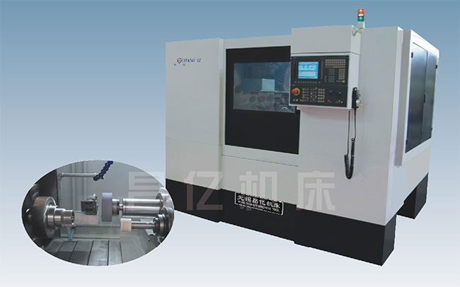
Changyi’s MKF2110 addresses internal bores, internal tapers, stepped holes, inner and outer end faces and outside diameters. Its table gives an ID range of 10–100 mm and maximum ID depth of 120 mm. The separate OD range is 15–150 mm, with a maximum grinding length of 100 mm. Put both features, their datums and the chucking area on the application drawing; an ID-depth limit is not an OD-length allowance.
The manufacturer identifies X as the feed axis and Z1/Z2 as grinding-wheel axes, with two-axis coordinated motion. Plan which wheel handles each surface, dressing access, withdrawal and possible interference before treating the machine as a complete one-clamping process. The described hydraulic chuck can be supplemented by a part-specific fixture, but the offered chuck, jaws and workholding need their own specification.
The source lists grinding-wheel motor 1 at 2.2 kW and motor 2 at 7–22 kW. The associated motor-speed entries are 2800 rpm and 1000–42,000 rpm; the workpiece entry is separately 0–600 rpm. Obtain the actual motor, spindle/quill, wheel and allowed operating speed for each operation rather than assigning the higher speed or power to every bore or outside surface. The 7–22 kW range does not define a continuous/peak duty pair.
Catalog specifications
- Controlled axes / described linkage
- X, Z1, Z2 / two-axis linkage
- Internal grinding diameter / maximum depth
- 10–100 mm / 120 mm
- Outside grinding diameter / maximum length
- 15–150 mm / 100 mm
- X stroke / Z1 and Z2 strokes
- 450 mm / 400 mm each
- Workpiece rotation
- 0–600 rpm
- Wheel motor 1 / motor 2 power
- 2.2 kW / 7–22 kW; selected motor/duty to confirm
X stroke is 450 mm; Z1 and Z2 strokes are each listed as 400 mm. These machine movements do not enlarge the stated grinding envelope. The servo rows are labelled as power but use N·m, so no servo-power value is adopted here. Resolve that unit conflict in the build sheet. The catalog body is 2800 × 2400 × 2600 mm and mass 4200 kg; loading, coolant, maintenance and extraction space need the installation layout.
The table publishes 5 µm positioning and 2 µm repeat-positioning entries for X/Z1/Z2. Its separate processing section lists ID/OD roundness 2 µm, cylindricity 3 µm, concentricity 3 µm, Ra0.4 µm and 4 µm perpendicularity. Those manufacturer references lack a complete part, wheel and measurement protocol here. They are not CNCVerified measurements or unconditional acceptance limits for a customer component.
Agree a representative hardened component, stock allowance, wheel specification, dressing schedule, clamp force, coolant condition and measuring method. Inspect bore-to-OD relationships and the released end face after the full sequence, then record loading, dressing, grinding, measurement and rejects over the agreed run. Decide explicitly whether all critical surfaces remain in one clamping and how the datum is recovered if the part is reseated.