
DMTG turning
DMTG DL-25MH
General Technology Group Dalian Machine Tool Co., Ltd. · Dalian
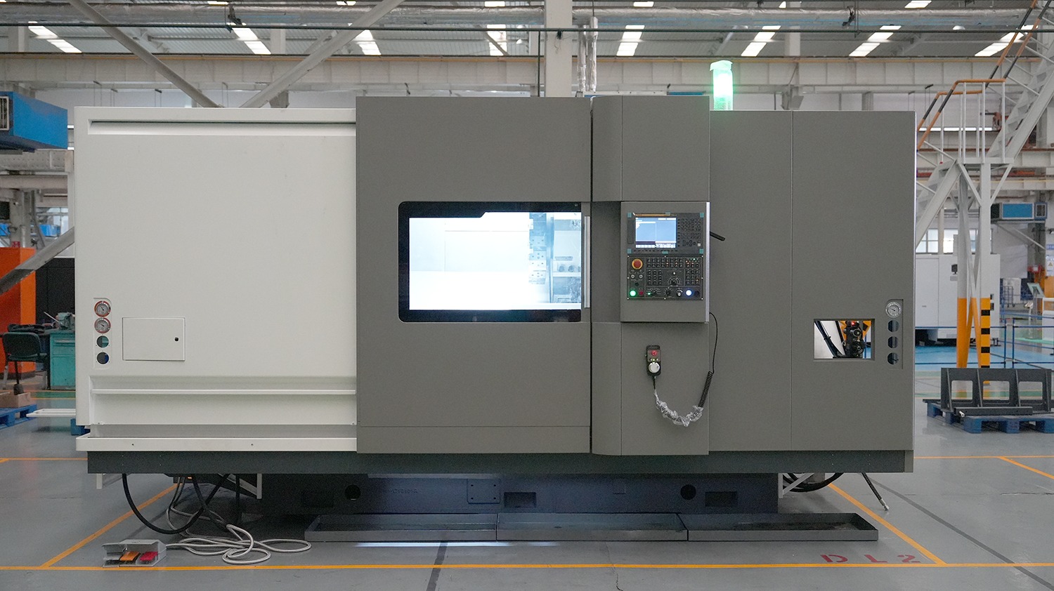
- Maximum swing over bed520 mm
- Maximum shaft / disc turning diameter310 / 500 mm
- Turning length alternatives1000 / 1500 mm; choose one build
- Spindle nose / chuckA2-8 / 10 inch
- Spindle speed entry3500 rpm; minimum not specified
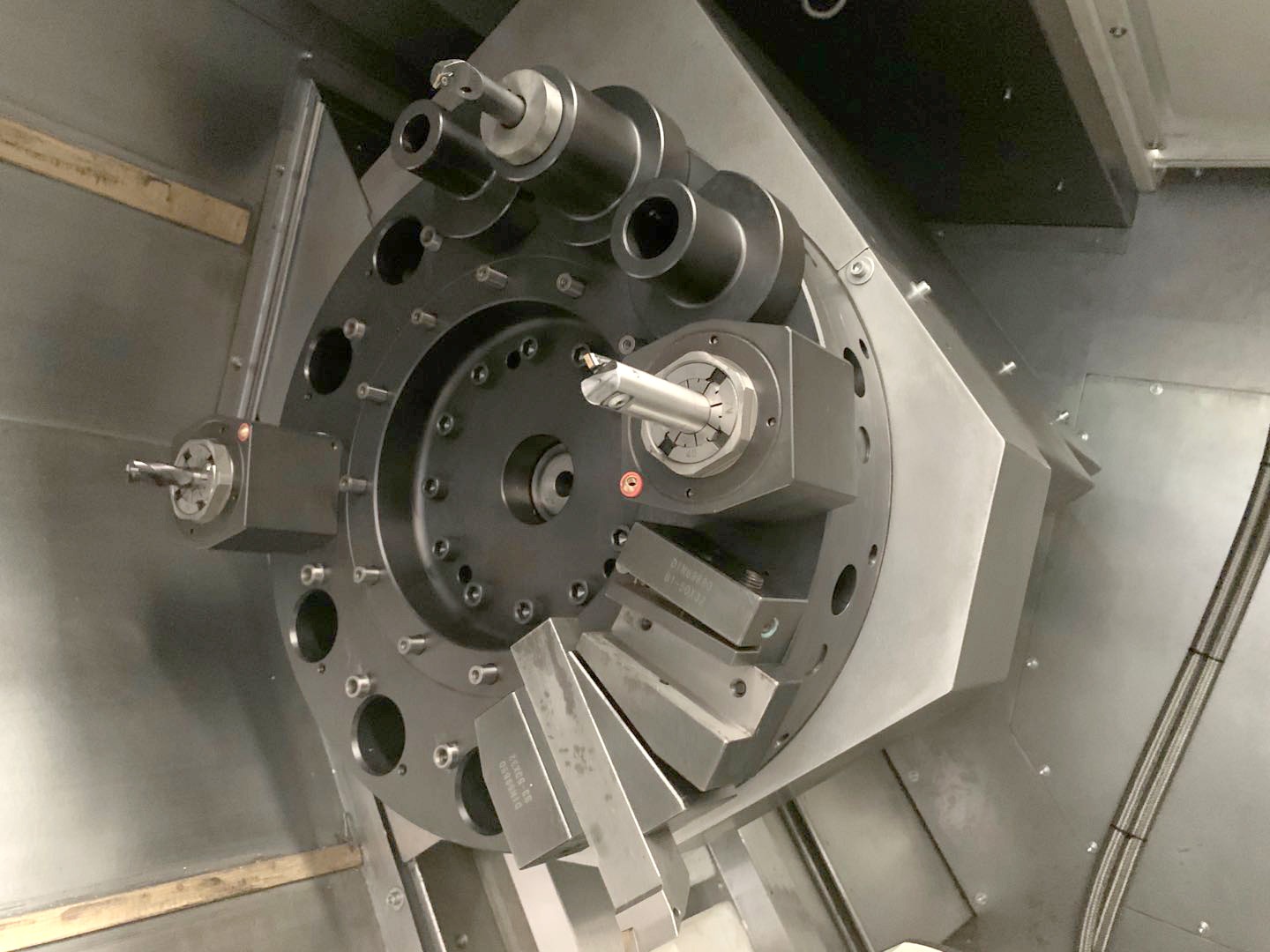
DL-25MH is the live-tooling version in the DL-25M/MH table. It specifies 12 driven-tool turret positions and C-axis entries, making the first procurement question which axial/radial holes or other features can be reached while the part remains gripped. The source does not establish a Y axis, second spindle or a completed process for every cross-hole geometry.
MH lists 520 mm swing over the bed but maximum shaft/disc turning diameters 310/500 mm; the M column’s 520 mm disc value should not be copied here. Select either 1000 or 1500 mm turning length and the corresponding 1040/1600 mm Z travel. Draw jaws, largest holder, saddle and support together; 260 mm X travel and a catalogue cutting diameter do not prove collision-free live-tool access.
Spindle references are A2-8, 10-inch chuck, 87 mm bore and 3500 rpm, with 18.5/22 kW motor pair lacking duty labels. Bar capacity is 74 mm only with the specified through-hole hydraulic chuck; through-hole chuck/cylinder and feeder equipment are configuration items. The C-axis entries are 44 arcseconds positioning and 18 arcseconds repeatability, not a guarantee of the position tolerance of a finished milled feature.
Confirm the offered live-tool holders, drive speed/torque, control cycles and spindle/C-axis clamping with FANUC 0i-TF(1) Plus or Siemens 828D. Settle the box-way versus linear-guide references and length-specific rapids in one build sheet. Trial the most interfering driven operation, index/restart and chip removal using the actual material and jaws; inspect feature relationships to the turned datum after release. Include tooling, loading and inspection when agreeing cycle time rather than quoting the turret-index entry.