

General Technology Group Dalian Machine Tool Co., Ltd. · Dalian, Liaoning
DMTG: choose the operation.
DL-25M, DL-25MH or VDLS850? Choose around your grip, features and datum.
Manufacturer model material and dated corporate evidence reviewed 8 October 2026
Start with the feature that changes the setup.
Dalian Machine Tool’s present company describes CNC machines, flexible manufacturing systems, automated equipment and functional components. The three reviewed models here cover a narrower decision: whether to turn the part with fixed cutting tools, add driven-tool operations while it remains gripped, or transfer it to a vertical machining centre. They are not an inventory of the complete factory catalogue.
Diameters, bores, faces and turned threads
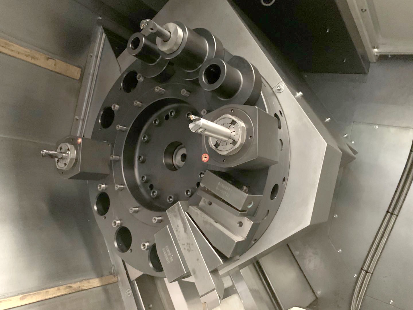
Start with DL-25M and its 12-position hydraulic turret. Put the jaw grip, support and each turning tool on the setup drawing. A tool station is not a driven-tool capability.
Cross-holes or other driven-tool features on a turned part
Review DL-25MH, which specifies a 12-position live-tooling turret and C-axis entries. Confirm holder access and the required control functions; the source does not establish a Y axis or a second spindle for this model.
Milled faces, pockets or a separate fixture operation
Review VDLS850. Draw how the turned datum will be located and checked in its fixture. A second machine may improve access, but it introduces another grip and a datum transfer to qualify.
DL-25M and DL-25MH: the turret is the first difference.
Both catalogue columns give 520 mm bed swing, 310 mm shaft turning diameter, a 10-inch chuck, A2-8 nose, 87 mm bore and a 3500 rpm spindle-speed entry. Disc turning diameter differs: 520 mm for M, 500 mm for MH. Bed swing and cutting diameter are separate limits; include the jaws, holder and saddle in the clearance review.
The published 1000/1500 mm turning lengths and 1040/1600 mm Z travels are alternative lengths shared by the two columns. Do not combine the longer cut with the shorter machine’s footprint. Long parts need a support plan: both columns list a 100 mm tailstock quill and 139 mm quill travel, which do not establish the permitted support load.
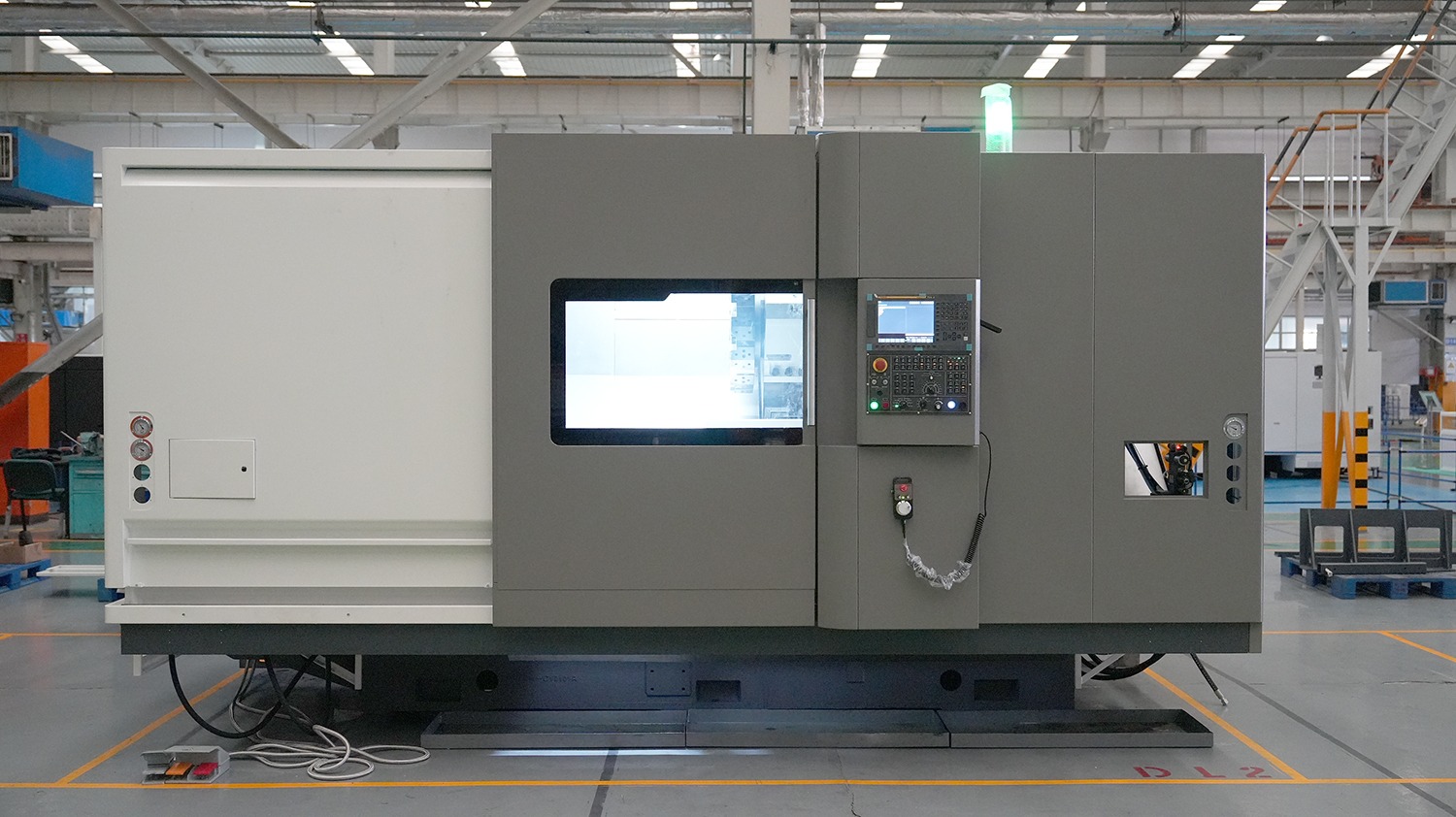
| Decision | DL-25M | DL-25MH |
|---|---|---|
| Turret | 12-position hydraulic | 12-position live tooling |
| Shaft / disc turning diameter | 310 / 520 mm | 310 / 500 mm |
| Spindle motor entry | 15/18.5 kW | 18.5/22 kW |
| C-axis specification | Not listed in M column | 44″ positioning / 18″ repeatability |
| Control alternatives | FANUC 0i-TF(5) Plus or Siemens 828D | FANUC 0i-TF(1) Plus or Siemens 828D |
Swipe the comparison on a phone. The motor pairs have no duty labels in this table; obtain the offered motor/drive curve rather than assigning continuous and peak ratings. Angular positioning entries describe the axis, not the location tolerance of every cross-hole.
One grip still needs a complete tool plan.
For MH, separate axial and radial driven operations. Draw tool reach, holder body and jaw interference, then ask for live-tool speed/torque, engagement limits and the actual milling/drilling cycles. The configuration material lists axial and radial holders and optional extras, but does not prove that a particular part can be completed without reclamping.
A void left for a large holder consumes usable stations. Include turning tools, drills, taps and inspection access in one turret layout. Review spindle orientation, C-axis clamping and restart with the exact control package. The 12-position count and indexing time cannot determine the accepted part cycle.
For bar work, specify the whole through-hole chain.
The 87 mm spindle bore is not a 87 mm bar-feed capacity. The catalogue’s 74 mm maximum bar entry is explicitly conditional on a through-hole hydraulic chuck. Its configuration image lists a non-through-hole hydraulic chuck as standard and the through-hole chuck/cylinder as options. Ask for the chuck, drawtube, cylinder, liner and feeder arrangement together; bar length, guidance and rotating-stock safety need their own review.
Guideway descriptions also need one quoted answer. The technical table lists box ways and optional linear guides for the 1000 version, with X/Z rapids of 12/12 and 24/16 m/min respectively. The overview and configuration image describe linear guides more generally. Obtain a model-length-specific build sheet that settles guideways and rapids rather than treating both references as one standard machine.
For rear chip-conveyor builds, the published body envelopes are 5010 × 2020 × 2110 mm for the 1000 length and 5200 × 2020 × 2110 mm for 1500, with listed masses 7800/8300 kg. Add door, loading, tailstock/rest, bar-feeder and service access. A rear-conveyor body dimension is not a complete automated-cell layout.
VDLS850: fit the loaded fixture, then the cutting tool.
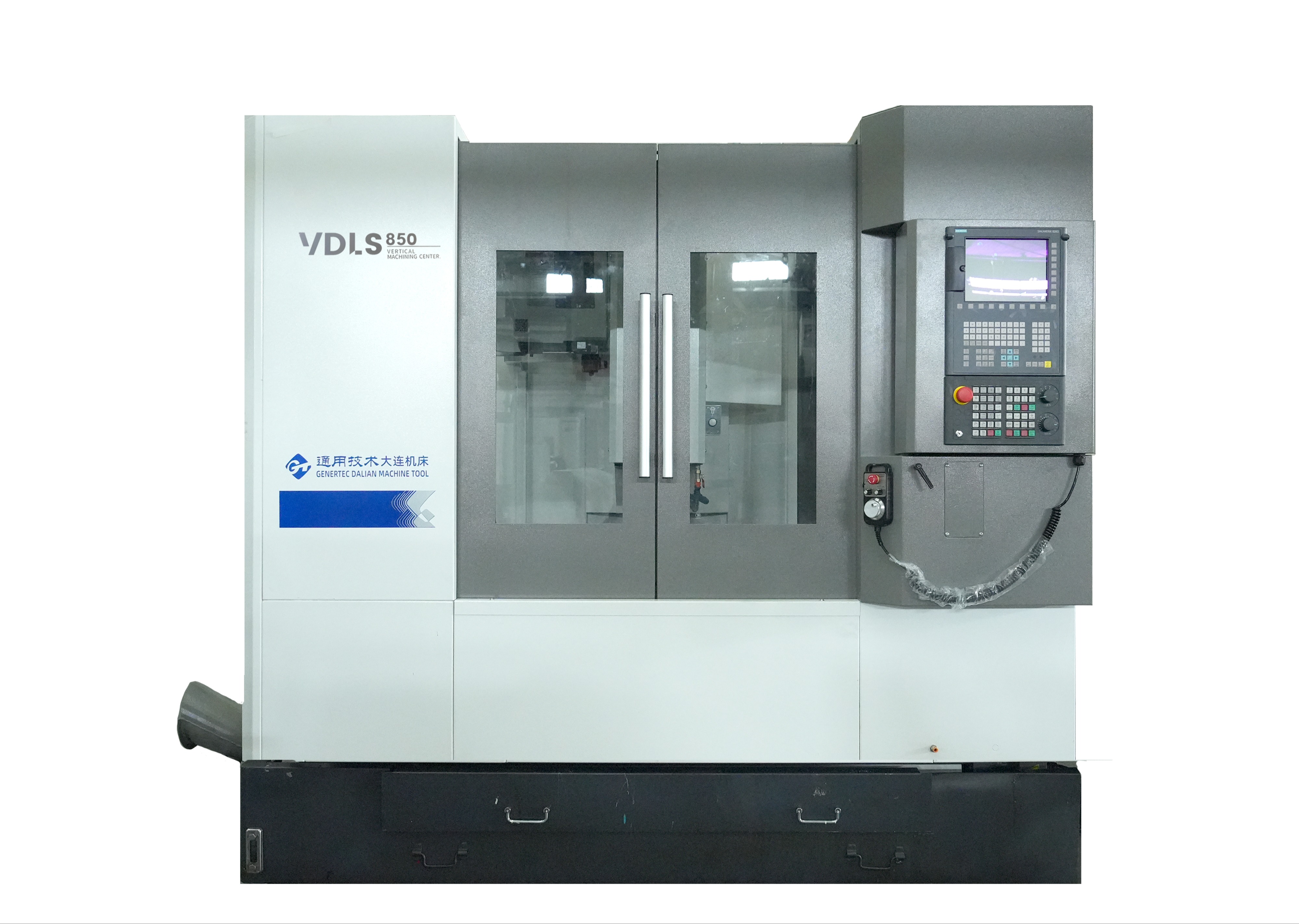
The exact VDLS850 table gives X/Y/Z travel of 860/510/560 mm, a 1000 × 500 mm table and 600 kg maximum load. Include the part, fixture, vice, clamps and any rotary equipment in that load. These dimensions differ from generic VMC850 figures; use the exact VDLS850 build rather than transferring another model’s 800/500/500 travel.
- Height and reach
- 145–705 mm spindle-nose-to-table distance; 607 mm spindle-centre-to-column. Combine fixture height, tool/holder gauge length and required approach before accepting the work envelope.
- Spindle choice
- BT40 / No.40 (7:24), 12000 rpm direct drive; 8000 rpm belt drive is an option. The 7.5/11 kW pair is not duty-labelled. Agree one drive, its torque curve and cutting trial.
- Tool loading
- 24-tool arm magazine, 8 kg maximum tool mass. The table gives 78/155 mm diameters with/without adjacent tools; settle slot occupancy and holder clearance on the offered magazine drawing.
FANUC 0i-MF(5) Plus, 0i-MF(1) Plus, Siemens 828D and Mitsubishi M80B appear as controller alternatives. Specify the exact control, cycles, postprocessor and supplied measurement equipment. X/Y/Z rapids of 36/36/30 m/min and a 2.7-second tool-to-tool entry are separate motions, not chip-to-chip time or the full loading-to-finished-part cycle.
The catalogue’s 0.008 mm axis positioning and 0.005 mm repeatability entries cannot alone guarantee a finished pocket, bore or transferred datum. Agree warm-up, alignment, tooling and measurement conditions. The listed body is 2496 × 2530 × 2679 mm at 5600 kg; loading and maintenance clearance must be added to the installation drawing.
Open the reviewed VDLS850 specification ↗Qualify the datum through the real operation sequence.
Turned part with live-tool features
On MH, run the intended jaws and the most interfering axial/radial holder. Inspect the relationship of driven-tool features to the turned datum after release. Include support, tool changes, chip removal and controlled-stop recovery in the trial.
Turning followed by vertical milling
Transfer a representative turned blank to the VDLS fixture. Record locating surfaces, grip force and approach; inspect milled-feature position against the turned datum after unclamping. Confirm the second setup’s repeatability rather than adding two machines’ axis figures.
Record material, blank condition, tool wear limits, critical dimensions and measurement equipment. Agree whether acceptance includes first-off parts, repeated loading, a batch and changeover. For a proposed feeder, parts catcher or flexible cell, identify the integrator, interfaces, guarding, fault recovery and delivered scope separately from the base machine catalogue.
The current company dates from 2019; the predecessor history is older.
The official profile identifies General Technology Group Dalian Machine Tool Co., Ltd. (通用技术集团大连机床有限责任公司), established in April 2019 through reorganisation of the former Dalian Machine Tool Group. It describes two manufacturing bases at Dalian DD Port and Wafangdian. Historical achievements of predecessor factories should not be presented as the incorporation date of this current company.
A February 2026 procurement notice on Genertec’s procurement platform independently names the same current entity in an external-component purchasing project. This supports the legal-entity identification at that date; it is not an equipment certification, independent factory audit, stock confirmation or proof of a delivery commitment.
Before purchase, identify the legal seller, actual build responsibility, model suffix/length, control, chuck/turret or spindle package and serial-number documentation. Agree destination utilities, geometry/process acceptance, training and spares/service responsibilities in the quotation. A group affiliation or a catalogue photograph does not settle those contract items.
Send the drawing with the proposed grips.
Include material and blank, turned diameter/length, disc or shaft geometry, datum and tolerance relationships, jaw/support plan and the live-tool features, if any. For bar work, specify stock diameter/length and the requested through-hole/feeder chain.
For a VDLS operation, add fixture/part mass and height, tool/holder list, transferred datum, spindle/control preference and loading method. State batch mix, the representative trial, inspection conditions, destination utilities and responsibility for any automated equipment.
Prepare a DMTG RFQ ↗