

安阳鑫盛机床股份有限公司
Anyang, Henan · horizontal and special-purpose lathes
Anyang Xinsheng: choose the support before the swing.
A small turned shaft, a multi-ton rotor and a valve ball need different setups. Compare the bed, cutting reach and support arrangement before choosing the spindle.
Individual manufacturer tables, original photographs and 2025 company disclosure reviewed 8 October 2026
Three workpieces, three different questions
- Small shaft or disc
- CK6142 economical CNC lathe ↗
Check Ø420 mm swing over the bed against Ø210 mm over the slide, then check the selected bed's usable cutting length. Include chuck jaws, tailstock and tool approach in the section drawing.
- Long, heavy shaft
- CK61160, 32/63 t configurations ↗
Begin with supported mass, centre of gravity, steady-rest positions and lifting. The two load versions have different motors, speed ranges and tailstock quills; they are not one combined specification.
- Valve-ball exterior
- C65 spherical-turning family ↓
Specify the sphere diameter and the ball's datum/support arrangement. This is a spherical exterior route, not evidence of internal ball machining or a finished sealing/leak-test result.
The manufacturer's range also includes conventional horizontal, pipe-threading and other specialised machines. A stated family or application is a starting point for an exact build review, not confirmation that every operation is standard on the two CNC references here.
CK6142: the bed length is not the cutting length
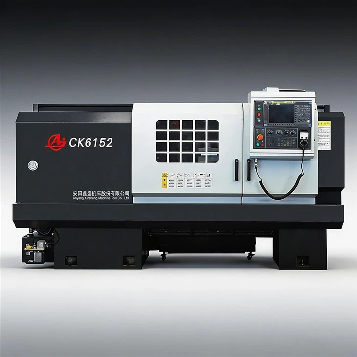
The CK6142 table offers six workpiece-length references: 500, 750, 1000, 1500, 2000 and 3000 mm. In the same order, its maximum cutting-length row gives 330, 580, 830, 1320, 1830 and 2830 mm. Select one matched pair; do not turn the 3000 mm workpiece reference into a 3000 mm continuous cut.
The base CK6142 column lists A2-6 spindle nose, Ø58 mm bore and stepless 27.5–2200 rpm. The adjacent CKP6142 is a different drive reference: four manually selected ranges with stepless speed within each, 14–1600 rpm. The CK6152 columns also have different swing, spindle interface and bore. Keep the suffix and column visible on the quotation.
A Ø58 mm spindle bore is not an approved bar-feeding capacity. Confirm chuck passage, drawtube or liner, actual stock straightness and rear support. For a long shaft, show the live centre and rest locations, available tool clearance and the setup at the furthest cut.
Check the standard tool and support package
The CK6142 table lists a four-station electric vertical toolpost, 25 × 25 mm tool shank, Ø80 mm tailstock quill, 150 mm quill travel and Morse 5 taper. A listed turret repeatability is not whole-machine positioning accuracy. Six-station carriers, rests, chip handling and cabinet cooling require their own option confirmation. The source lists FANUC 0i-TF / GSK980TD alternatives; name the selected control and software in the offer.
CK61160: keep the 32 t and 63 t builds separate
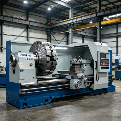
The manufacturer describes an HT300 three-guideway base, rack-and-pinion Z feed, ball-screw X feed and inlaid steel guides with automatic lubrication. The spindle range and maximum torque are separate references: maximum torque is not available at every spindle speed.
On a phone, swipe sideways to compare the two load configurations.
| Selected configuration | 32 t | 63 t |
|---|---|---|
| Workpiece mass reference | 32 tonnes | 63 tonnes |
| Swing over bed / carriage | Ø1600 / Ø1250 mm | Ø1600 / Ø1250 mm |
| Workpiece-length choices | 4000–20,000 mm | 4000–20,000 mm |
| Spindle motor | 75 kW | 144 kW |
| Speed range | 0.8–160 rpm | 0.5–125 rpm |
| Maximum spindle torque | 80 kNm | 120 kNm |
| Maximum cutting-force reference | 80 kN | 120 kN |
| Tailstock quill diameter | Ø300 mm | Ø560 mm |
The 4000–20,000 mm range represents bed selection, not a guaranteed full-length cutting stroke on every machine. Request the loaded arrangement, tailstock and rest movements, support reactions and allowable offset. Include fixture mass and operating forces in the support review; a catalogue workpiece mass is not the foundation calculation.
The standard rest has its own diameter range
The English build reference lists an open steady rest for Ø650–1200 mm, a manual four-jaw heavy faceplate, four-station electric toolpost and FANUC 0i-TD. A smaller journal may require a different rest or an agreed temporary support surface. A closed rest, Siemens control, external grinding head and live-milling attachment are separate options. Ask for their exact drives, travel, mounting and acceptance before adding them to the machining sequence.
A valve ball needs a sphere-specific route
The C65 page covers external spherical turning for valve-ball cores and gives four distinct size references. C6555 lists Ø50–550 mm spheres, 6–800 rpm and an 11 kW main motor; C6595 lists Ø260–900 mm, 3.15–315 rpm and 22 kW. C65160 lists Ø1000–1600 mm and C65180 Ø1200–1800 mm, both 3.15–315 rpm and 30 kW. The C6595 table's maximum is 900 mm despite the model name; do not infer 950 mm.
The source describes rectangular bed guides and a three-support spindle. It mentions turning and grinding operations, but does not establish which grinding attachment is included in a particular order. Provide the ball drawing, locating surfaces, bore/stem features, roughing allowance and permitted gripping marks. Ask for the exact sphere-generation setup, tool sweep and any finishing attachment.
Define roundness, profile and finish over the agreed measurement area, including how the ball is released and re-referenced. A machined exterior does not establish sealing performance, coating integrity or valve pressure qualification. Those need their own process and assembled-valve acceptance.
Use a trial that exposes the setup's weak point
For CK6142, reach the end of the actual cut
Trial the selected bed and tailstock position with the intended chuck, tools and longest unsupported length. Include the shoulder or bore that is hardest to reach. Measure runout and size after release where clamping distortion matters.
For CK61160, prove support and low-speed cutting together
Load a representative shaft using the agreed lifting and resting plan. Run the difficult interrupted cut or roughing section at the proposed speed, engagement and tool projection. Record vibration, rest adjustment, chip removal and temperature before finishing the agreed datum relationships.
For a valve ball, inspect the surface as a sphere
Agree sphere fitting, measurement locations and fixture removal before the trial. Separate form error from surface finish and the later sealing test. Include cleaning, handling, support resets and inspection in elapsed cycle time.
Manufacturer IT-grade and roughness references describe its published capability claims. They do not replace acceptance on your material, geometry, tool, fixture and thermal conditions.
Identify the current company before relying on the long history
The company is 安阳鑫盛机床股份有限公司 in Anyang, Henan. Its 2025 annual report, company overview on page 5 identifies the same Chinese/English entity and records incorporation on 31 December 2002 and NEEQ code 831577. The manufacturer's earlier toolmaking and lathe history refers to predecessors; 1946 is not this legal entity's incorporation date.
The report describes machine-tool development, manufacturing and sales, overhaul and retrofit, plus machine parts and tools. These are business-scope statements, not independent inspection of a proposed machine or a model accuracy certificate. Match the contract entity, chosen build revision and actual manufacturing/installation responsibilities before purchase.
Request foundation reactions, lifting points, machine and accessory layout, lubrication schedule, control backups, spare-part identification and destination-specific commissioning/training. Heavy-bed transport and alignment, rest servicing and a grinding/milling option have separate support needs; agree their scope and response arrangements in writing.
Send the loaded setup with the difficult feature
Include blank and fixture CAD, material/hardness, total supported mass, centres and rest positions, selected bed/cutting length, chuck interface and passage, tool projection, roughing allowance, critical datums and finish, chosen control/options, trial inspection plan, output target and installation destination. For a valve ball, add sphere size and locating/sealing requirements.
Xinsheng RFQ ↗