

DEKAY · 德凯
Yuyao, Ningbo, Zhejiang
DEKAY: prove the machining process before adding ultrasonic capability
Compare conventional vertical machining with a five-axis ultrasonic route. Define the material, tool access and inspection result first, then test the proposed configuration on representative parts.
Official model material and original V855 brochure reviewed 8 October 2026
What does the proposed process need to improve?
Conventional machining is the starting point
For accessible milled, drilled, bored and tapped features, compare the V855 setup against the drawing, material and tooling. Determine whether the limiting issue is access, surface condition, tool wear, cycle time or dimensional control.
Five-axis access and ultrasonic action are separate questions
FA-UM800 combines an A/C cradle with an ultrasonic tool system. Check whether the geometry needs rotary access, and separately whether ultrasonic assistance improves the required result on your material. A five-axis layout and a frequency specification alone do not establish that improvement.
V855: a defined conventional tool and control package
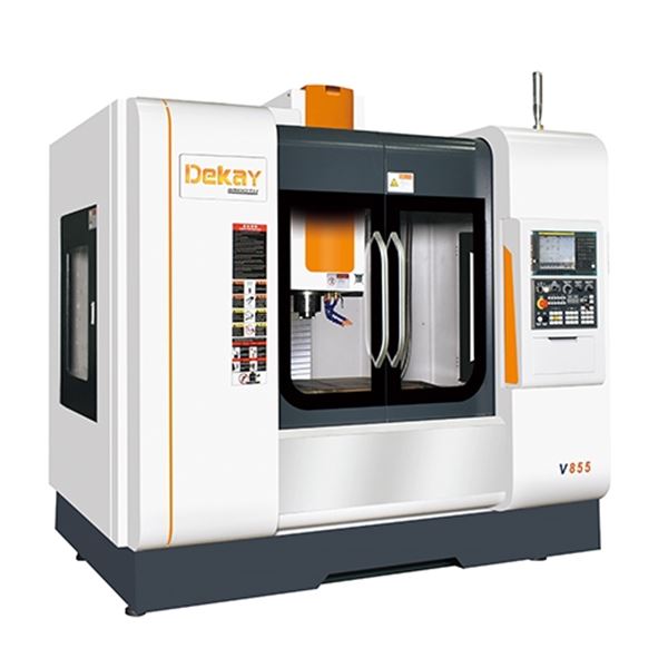
V855 brochure column
- X / Y / Z travel
- 800 / 550 / 550 mm
- Table / load
- 1000 × 550 mm / 500 kg
- Spindle nose to table
- 120–670 mm
- Standard spindle
- BT40; 8000 rpm; 7.5 kW entry
- Magazine / standard control
- 24 tools / Mitsubishi M80B
- Dimensions / mass
- 2600 × 2500 × 2700 mm / 5 tonnes
The original brochure separates the V855 column from larger V1160, V1370LH and V1580LH machines. Their spindle interfaces, loads and dimensions are not V855 specifications. Check the combined workpiece/fixture mass and the complete tool approach within the nose-to-table range.
FANUC control, faster direct-drive/built-in spindle packages, through-spindle coolant, a fourth-axis table, workpiece probing and tool setting appear as options. Select one exact package and verify the controller functions and postprocessor needed for the part. An optional probe is not a supplied inspection result.
FA-UM800: approve rotary access and the ultrasonic tool chain
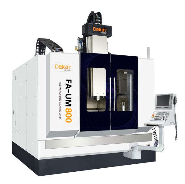
Geometric and rotary envelope
- X / Y / Z travel
- 850 / 1000 / 600 mm
- Spindle nose to table
- 180–780 mm
- Cradle table / listed load
- Ø800 mm / 1200 kg
- A / C movement
- ±120° / continuous rotation described
- Spindle
- HSK-A63; 18000 rpm; 30 kW entry
- Dimensions / mass
- 3300 × 4200 × 3500 mm / 17.5 tonnes
Ultrasonic equipment
- Published frequency
- 28 ±0.3 kHz
- Published output power
- At least 50 W
- System components described
- Generator, ultrasonic toolholder and transmission module
- Magazine shown as optional
- 32 tools; 5 kg; 300 mm length; Ø80 / Ø100 mm with adjacent empty position
- Control shown as a choice
- LNC N5E
Approve the combined blank/fixture envelope throughout the programmed A/C movement. Request allowed mass, center-of-gravity and moment conditions at the required tilt; the table-load entry alone does not define them. Check tool, spindle and enclosure clearance throughout the path.
The ultrasonic frequency is not tool-tip amplitude. Request the proposed holder/cutter combination, amplitude and operating conditions, power-delivery definition, cooling and tool-setting procedure. The published spindle speed, power and torque entries do not establish that all maxima occur at the same operating point.
Design a comparison that can answer the process question
Same material and feature
Provide the grade, hardness/material state, geometry and difficult features. Agree cutter, fixture, coolant and measurement conditions. Where practical, compare the proposed ultrasonic process enabled and disabled on equivalent specimens.
Measure the drawing's criteria
Specify dimensional, surface and edge-condition requirements relevant to the actual part. Record cutting settings, ultrasonic conditions, tool wear and rejects. Do not substitute a generic material demonstration for the ordered component.
Keep the complete workflow
Separate cutting from loading, tool changes, inspection and setup. Repeat enough representative work to assess the agreed production objective. If the benefit depends on special tooling, include its supply, replacement and setting procedure.
Acceptance should state the component result and the tested equipment configuration. A successful rotary motion demonstration proves access only under that setup; it does not prove ultrasonic benefit or a production-rate guarantee.
Keep three measurement layers distinct
| Layer | What it describes | What it does not establish |
|---|---|---|
| Machine-axis specifications | FA-UM800 gives a linear positioning entry over 300 mm and separate rotary-axis entries | Finished-part tolerance including tooling, clamping, cutting and measurement |
| Scanning measurement equipment | The page gives separate accuracy and resolution entries for a scanning instrument | That instrument is included, or that resolution equals measurement accuracy |
| Part acceptance | Your specified features, datums, inspection method and report | Automatic conformity from either catalog entry above |
Swipe the measurement table on a narrow phone.
Identify the instrument and uncertainty appropriate to the part, the machine test method and the report supplied with the trial. Keep control calibration, probe/scanner scope and independent part measurement distinct in the purchase documents.
DEKAY's CNC equipment business
Official material identifies 宁波德凯数控机床有限公司 in Yuyao, Ningbo. The company describes CNC equipment development, manufacturing and sales support, with a catalog including five-axis, linear-motor, mold-machining, heavy gantry and gear-processing machines.
The national standards record for GB/T 42707.2-2024, published 26 October 2024 and effective 1 May 2025, names the company among drafting organizations for CNC remote fault diagnosis and predictive maintenance. Drafting participation is not model certification or proof that remote maintenance is included in the quoted machines.
The process-trial and measurement guidance above is CNCVerified's editorial analysis. Name the contracting entity, control/software licenses, ultrasonic tools, training, backups and destination service responsibilities in the proposal.
Request a material-and-feature trial
Attach the part drawing, material state, fixture concept and inspection criteria. State whether the objective is conventional machining, rotary access or an ultrasonic process improvement, and request the exact tested configuration and tooling package.
Send DEKAY RFQ ↗