

Guangzhou Hachi CNC Machine Tool Co., Ltd.
Long-profile machining
HACHI: will the tool reach every feature of your long profile?
A long X stroke does not establish side access, both-end reach or a stable released part. Compare HCA4500 vertical machining with HGE4D6300's orientation-dependent range, then prove the support and clamp plan.
Official company pages and model-specific parameter images reviewed 8 October 2026
Mark the feature span, not just the blank's length
HACHI's catalogue includes three-axis and multi-axis profile machining, vertical centres and gantry equipment. It describes milling, drilling and tapping of copper, aluminium and alloy profiles, with applications including rail transport, vehicle parts and linear modules. These two machine references require different tool-access checks.
| Drawing check | HCA4500 | HGE4D6300 |
|---|---|---|
| Published X reference | 4500 mm linear travel | 6400 mm for vertical machining; 5970 mm spindle-nose span for horizontal machining |
| Y / Z travel | 550 / 700 mm | 600 / 700 mm |
| Tooling reference | BT40, up to 12000 rpm; 24-tool disc magazine | BT40 / BBT40 interface, up to 20000 rpm; 24-tool disc magazine |
| Main configuration question | Can each top-access feature be reached without a clamp or tall section blocking the holder? | Does each side/end operation fit the rotary head, holder and orientation-specific reach? |
| Existing model page | HCA4500 ↗ | HGE4D6300 ↗ |
On a small screen, swipe the comparison horizontally.
For HGE4D6300, the 6400 mm entry is not a universal horizontal usable length or a promise to finish both ends of any 6400 mm blank. Supply the coordinates of the outermost features, the tool and holder lengths, and the clamp layout. Confirm the rotary working range, positioning/continuous-motion modes and the collision envelope in the proposed configuration.
Keep the photographed series and the parameter column separate
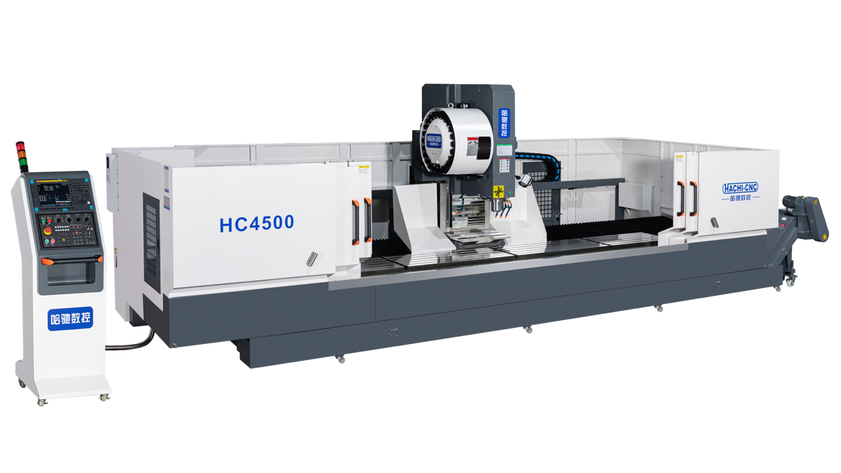
HCA4500: top-access operations on a supported profile
The page presents the classic series for milling, drilling and tapping profiles, with a 150 mm spindle body and BT40 tooling. Its 11/18.5 kW spindle-power pair has no duty basis stated in the table; select the motor/drive rating from the cutting requirement and obtain its applicable duty and torque curve.
The 24-position magazine must hold the real drilling, tapping and milling tools, including any sister tools. A 700 mm Z stroke is not a 700 mm permitted profile height: supports, part section, holder projection and working positions need a combined clearance drawing.
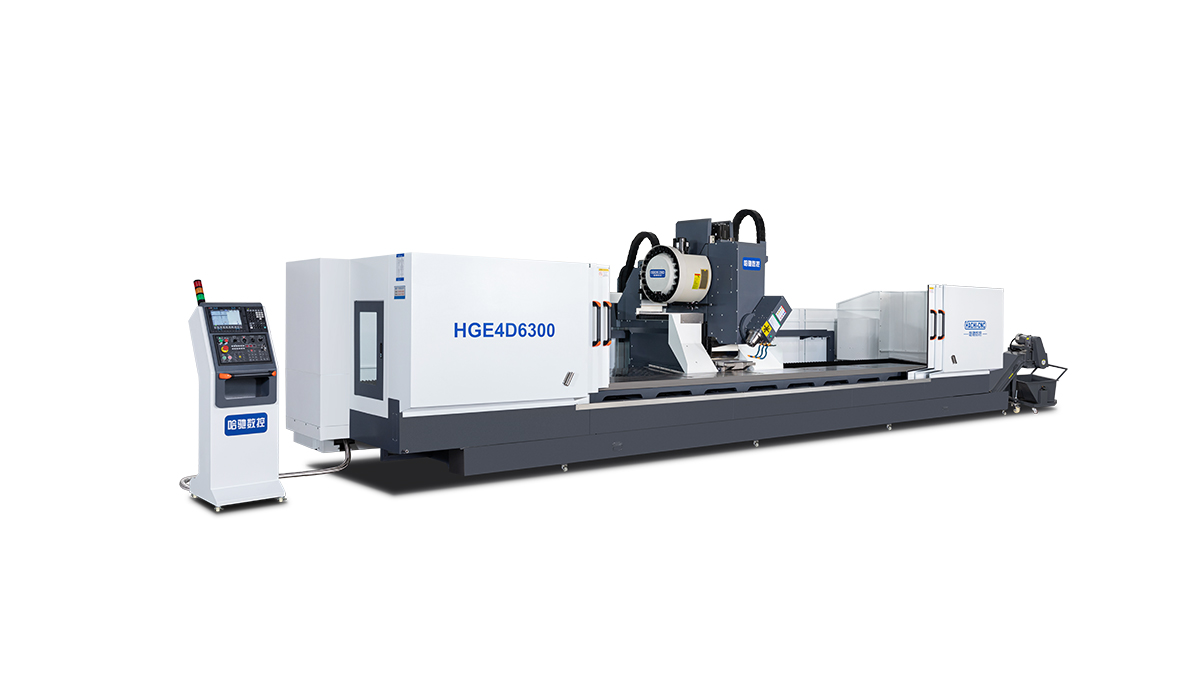
HGE4D6300: plan every machining orientation
The exact parameter image lists an 11 kW, 20000 rpm electric spindle, a 150 mm body and BT40/BBT40 interface. Changing orientation can bring a side feature within reach, but the holder, spindle body or fixture may become the limiting geometry. Review the swept volume with the longest tool and each support position.
The catalogue rapid rates are X 60 and Y/Z 28 m/min for both reviewed machines. They describe motion, not output from a completed long profile. Neither four-axis naming nor a larger X entry establishes a better cycle for the buyer's part without a real clamp-and-tool sequence.
The clamped profile and the released profile are different checks
- Thin or open sections
- Show wall thickness, section variation and contact faces. Agree pads, support spacing and clamping force so the setup locates the part without forcing it into a temporary shape. Inspect relevant dimensions after release; do not accept a straightness result measured only under clamps.
- Long rows of mounting holes
- Give a single drawing datum and the full feature coordinate span. If clamps must move or the part must be re-positioned, document how the datum is retained or re-established. Include features on both sides of the transition in the trial.
- End and side operations
- Show the tool approach, projection and cross-section at each end. For HGE4D6300, verify horizontal reach separately from vertical X travel. Decide whether a second setup is required before estimating cycle or ordering a fixture.
These are fixture-planning checks, not claimed HACHI production results. Obtain the allowable workholding load, moments, support layout and clamp package for the proposed machine; the reviewed pages do not provide a universal profile payload.
Use a drawing that exposes the difficult features
Section and blank
Material and condition, total length, wall thickness, mass, straightness/twist before machining, cut ends and cosmetic faces. Include actual section geometry rather than only a bounding rectangle.
Feature and tool map
Hole, thread and milled-face coordinates; approach direction; cutter/holder projection; minimum access and keep-out zones. Mark the two furthest features and the features nearest clamps.
Support and acceptance
Locating datum, pad/support and clamp coordinates, any change of setup, tolerances after release, batch mix and target accepted output. Define measurement over the entire length.
Accept the difficult end-to-end geometry first
Run the actual support and clamp sequence
Use a representative blank, tools and supports. Include side/end features, the longest tool, a necessary clamp move and part loading/unloading. Retain the program and fixture revisions so the demonstrated setup is the one supplied.
Measure after unclamping across the full span
Check far-apart hole locations, threads, machined faces and the required straightness/twist against agreed datums. Record the inspection method, support condition and temperature. If the profile is re-positioned, evaluate features across the datum transfer rather than only local distances.
Repeat across the production conditions
Include representative blank variation, tool changes, tapping/chip evacuation and a planned restart. Count accepted parts, rejects and interventions over elapsed time. Separate machine inspection from finished-profile acceptance: the parameter tables' 0.03 mm full-stroke X and 0.01 mm Y/Z positioning references are not a finished-part tolerance warranty.
Reserve space for the whole machine and the long part
The HGE4D6300 table lists approximately 11,000 mm overall length including the water tank and chip conveyor, and about 16,500 kg machine mass. The classic-series table instead shares broad length and mass ranges across HCA4500/6500; obtain an HCA4500-specific installation drawing before planning foundations or logistics.
Include blank staging, finished-part withdrawal, lifting, chip access and service clearances. Agree control/CAM and postprocessor scope, rotary configuration, electrical supply, coolant and destination service. A long component can require handling space beyond the machine's published footprint.
The company site identifies Guangzhou Hachi CNC Machine Tool Co., Ltd. A Guangzhou Science and Technology subsidy-list attachment names the same Chinese entity in its 2022 high-tech enterprise cultivation project, row 454. That historical entry supports entity context; it is not used as current certification or proof of a particular machine's performance.
Send the profile section and the farthest features
Attach the section and full-length drawing, material/blank variation, feature coordinates and approach directions, longest tools, support/clamp layout and setup changes. Include released-part tolerances, measurement method, batch mix, intended rotary configuration, complete installation/handling space and destination.
Send HACHI RFQ ↗