

北京工研精机股份有限公司
Beijing Precision Machinery & Engineering Research · Shunyi, Beijing
Gongyan: start with the optical surface, not the smallest number.
Spherical mirrors, flat optical surfaces and drilled housings require different machines. Match material, fixture and inspection to the process before comparing catalogue accuracy.
Individual original product tables and Beijing's May 2025 company visit reviewed 8 October 2026
Choose the surface and the manufacturing route
- Rotational optical surface
- SPHERE200 ↗
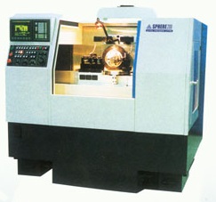
The original reference describes spherical mirrors and mirror finishing of flat and cylindrical surfaces, using an aerostatic spindle and rotary tool table. Begin with the substrate, clear aperture and required surface form.
- Flat optical surface or prism
- SQUARE-200 ↗
The 80/200/300 family has different travel, spindle-to-table height and cutter sweep. Indexing, turning conversion and a special CNC are optional packages; identify the required operation first.
- Holes and milled features
- FANUC α-D14MiA reference ↗
A BT30 drill/tap and milling route for a different job. Gongyan's page identifies FANUC as the manufacturer and describes its own agency sales/service role. It is not a Gongyan-built optical finishing machine.
The company also lists horizontal, vertical and five-axis machining centres, special machines and functional components. The three references below explain distinct processes; they are not a complete catalogue or proof that all optional operations coexist on one build.
SPHERE200: keep the rotary-table and no-table envelopes separate
The source lists 200 mm maximum workpiece swing with the rotary table and a 450 mm no-table alternative. Removing the table changes the configuration; it does not give the rotary-table build a 450 mm optical aperture. X/Z travel is 340/200 mm. Check the blank, chuck, tool holders and complete cut through the proposed surface profile.
The page describes an aerostatic spindle and rotary table, pneumatic chuck, fixed multiple-tool arrangement and closed-loop slide. Spindle position sensing is described, but a C axis is optional. Specify the actual positioning/indexing functions, tool-centre calibration and gripping sequence; do not assume a milling package or simultaneous multi-axis machining.
- Published test material
- Oxygen-free copper
- Surface roughness reference
- Ra ≤0.025 μm
- Roundness reference
- ≤0.3 μm on a Ø50 mm copper workpiece
- Published machine air pressure
- 0.6 MPa
These are different tests. Spindle/table axial and radial runout of ≤0.3 μm is a machine reference, not a guarantee of optical figure across your aperture. Agree material, tool, form measurement and release conditions for the actual mirror.
SQUARE: cutter sweep is not the workpiece envelope
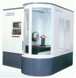
The source describes air-bearing spindle and table arrangements, with oxygen-free copper and aluminium as example nonferrous workpiece materials. The SQUARE-200 column gives 200 mm X travel, 100 mm Z travel, 200 mm spindle-centre height above the table and Ø300 mm cutter rotation. Cutter sweep is not a Ø300 mm finished-part capacity.
For a flat surface, show the entire fixture, clamping points, stock allowance and tool entry/exit. Check the surface remains accessible at its furthest edge without fixture collision. For a prism, define how each face is indexed and referenced; the high-precision indexing table is optional.
The family's Ra 0.01 μm figure is a manufacturer surface reference. Define the measurement instrument, evaluation length/filter, substrate and machining conditions for acceptance; do not transfer that figure to hardened steel, glass or an arbitrary coating.
α-D14MiA: a FANUC machine and a separate service arrangement
Gongyan's original page says this series is a FANUC product supplied through its agency sales and service. Treat that as a dated catalogue description: ask for current model availability, the actual seller, serial/build revision and who commissions and supports it at the destination.
Load the table and fixture together
The table reference is 650 × 400 mm with 300 kg uniformly distributed loading. Travels are X/Y/Z 500/400/330 mm. The listed 150–480 mm spindle-face-to-table distance excludes a specified high-column option. Include fixture, blank and longest tools in the clearance drawing; table area and travel are not interchangeable.
Make the occupied tool map
The reference uses a 14-position turret changer and BT30/P30T-1 interface, with Ø80 mm maximum tool diameter and a 250 mm length entry qualified by specification differences. The page gives separate 2 kg per tool/15 kg total and 3 kg per tool/22 kg total alternatives. Confirm one compatible package; never combine the largest per-tool and total figures.
Published spindle speed is 100–10,000 rpm and rapid feed 48 m/min. The 1.4 s entry is tool-to-tool change time, not a complete chip-to-chip or accepted-part cycle. Trial the deepest hole, thread and milled feature with chip removal, indexing and inspection included. The reviewed catalogue image is marked by a D21MiA filename, so it is not used as a D14MiA photograph.
For an optical surface, put the site conditions in the offer
Air at the machine
SPHERE200 lists 0.6 MPa; the reviewed SQUARE table does not publish a supply specification. Ask for the selected machine's required flow, filtration, drying, stability and response to loss of pressure. A compressor's nominal pressure does not establish acceptable air at an aerostatic bearing.
Heat, vibration and measurement
Ask for room conditions, warm-up/stabilisation, floor and vibration requirements, and how handling and inspection temperatures are controlled. The SPHERE reference's approximately 3 t mass and 1680 × 1400 × 1580 mm dimensions do not substitute for lifting, service-access or foundation drawings.
Agree tool setting, spare-tool strategy, chuck/fixture maintenance, parameters and software backups, operator training and metrology responsibility. Current utility and site requirements must come from the delivered build; do not design the installation from a family illustration.
Accept the optical surface on its drawing
Define what is measured
Provide substrate grade/coating, geometry, clear aperture, datum scheme, form and roughness limits. Agree edge exclusions and how form, waviness and roughness are separated. A roundness result on a Ø50 mm copper testpiece does not establish spherical figure over a larger mirror.
Machine with the final support concept
Use the intended chuck or fixture, real blank allowance and cutting tools. Test the difficult edge or slope, tool changes and repeated locating. Record machine/configuration, material, tool setting, air supply and thermal state.
Release, re-reference and inspect
Agree the inspection setup before the cut. Check the surface after release where fixture distortion matters, with instrument calibration and analysis settings recorded. For prisms, inspect relationships between faces; for a drilled housing, inspect the hole/datum relationships instead of borrowing optical-finish criteria.
Time the usable result
Include cleaning, loading, setting, cutting, release and inspection. Report rejects and repeatability across the agreed sample. Catalogue runout, rapid speed or motion resolution alone does not settle production output.
Separate the research company, machine builder and agent
The original company page identifies 北京工研精机股份有限公司 in Shunyi, Beijing, and describes precision/ultra-precision machine development and test laboratories. A Beijing government report dated 19 May 2025 records an official visit to the company, including workshops/laboratories. This supports company/site context; it does not certify a model's accuracy or a proposed order.
Use the exact legal seller and builder on the contract. Assign optical-process development, fixtures, metrology, machine acceptance, installation and warranty responsibility explicitly. For FANUC-supplied equipment, confirm the current agency/service arrangement separately from Gongyan's own ultra-precision range. General company capabilities and historical platform descriptions are not delivered-machine configuration records.
Send the surface drawing and how you will measure it
Include substrate/coating, blank and fixture, optical aperture or hole pattern, form/roughness and datum requirements, inspection instrument/method, sample and output target, desired machine/options, air/environment and installation destination. For α-D14MiA, add the occupied tool map, fixture mass and longest tool; for SQUARE, specify indexing or turning conversion where needed.
Gongyan RFQ ↗