

济南第一机床有限公司 · Zhangqiu, Jinan, Shandong
JFMT: place the wheel fixture before choosing the machining centre.
A BT50 wheel-oriented centre and a BT40 linear-guide centre solve different loaded setups. Compare minimum tool reach, fixture weight and occupied tools before comparing spindle speed.
Compare the two setups ↓Prepare a JFMT RFQ ↗
Individual manufacturer model tables and the parent’s 2025 issuer report reviewed 8 October 2026
Wheel machining is an application, not a complete process in one machine
JFMT’s published range includes wheel and brake-disc equipment, turning machines, machining centres and automation. The two models below are vertical machining centres. J1VMC1370W is described for wheel/rim machining with hardened cast guideways; J1VMC500 uses linear guides for general milling, drilling and related work. Neither model table establishes a complete wheel-turning, balancing or automated production line.
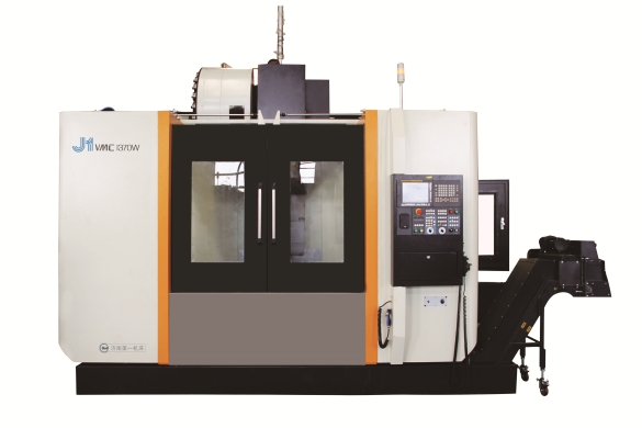
BT50 · hardened guideways · wheel-oriented envelope
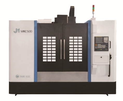
BT40 · linear guides · general machining envelope
On a phone, swipe the comparison. These are the exact model-table references; the delivered build and loaded arrangement must be agreed.
| Setup reference | J1VMC1370W | J1VMC500 |
|---|---|---|
| X / Y / Z travel | 1300 / 700 / 700 mm | 800 / 550 / 550 mm |
| Table / load | 1400 × 710 mm / 1000 kg | 1000 × 550 mm / 500 kg |
| Nose-to-table window | 450–1150 mm | 120–670 mm |
| Spindle-centre to column | 784 mm | 595 mm |
| Spindle reference | BT50 / 10,000 rpm / 18.5 kW | BT40 / 8000 rpm / belt drive / 7.5–11 kW |
| X / Y / Z rapids | 15 / 15 / 15 m/min | 36 / 36 / 24 m/min |
| Magazine | 24-position disc | 24-position disc |
| Listed control | Siemens 828D | FANUC 0i-MF |
The name J1VMC500 does not mean 500 mm X travel: its actual table gives 800 mm. Likewise, the larger 1370W stroke does not mean a short tool can reach a low fixture. Compare the full loaded assembly, not the model number.
The 450 mm minimum can decide the fixture
1370W: check the lowest surface first
With the spindle nose no closer than 450 mm to the table, a shallow blank on a low fixture may require a raised fixture or a longer tool assembly. Draw the actual nose, holder, tool tip, lowest cut and highest clamp. Raising the setup changes mass, leverage and withdrawal clearance; extending the cutter changes stiffness. Neither solution is automatically acceptable.
The manufacturer associates the Y envelope with 13–24 inch wheels and mentions a maximum wheel height of 13 inches. Treat these as application references, not an unconditional capacity. Obtain the complete wheel, fixture and tool interference study, including the rim/barrel and any rotary arrangement. A fourth axis or wheel fixture is not proved included by this table.
Twenty-four positions are not twenty-four unrestricted tools
- 1370W · heavier BT50 assemblies
- The table lists 15 kg tool mass and 300 mm maximum length. Diameter is Ø112 mm with neighbouring positions occupied, or Ø200 mm with adjacent positions empty. Lay out large face mills, boring heads and sister tools together before counting available positions. The 2.9 s tool-change reference is not a finished-wheel cycle.
- 500 · BT40 tool map
- The corresponding limits are 8 kg and 300 mm, with Ø78 mm occupied-neighbour diameter or Ø120 mm with adjacent positions empty. Its 2.0 s change reference excludes the rest of the route. Specify complete holder assemblies and the exact pull-stud interface; BT40 and BT50 equipment are not interchangeable.
- Power and floor space
- 1370W’s listed body is 3700 × 3400 × 4400 mm at 10 tonnes and 45 kVA; 500 is 2800 × 2400 × 3200 mm at 6 tonnes and 30 kVA. Check the 4.4 m height against crane, door and ceiling access. Body dimensions exclude whatever maintenance, tool handling or cell clearance the installed layout needs. The spindle power entries lack a stated duty definition; request torque and duty at the intended cut.
Accept the part after it leaves the fixture
Wheel route: make the datum chain explicit
Provide the blank, earlier turning operations, hub/centre datum and required hole pattern or milled feature. Trial the actual locating and clamping sequence. Inspect feature position relative to the agreed datum, burrs and any relevant form after unclamping. Specify any later turning, balancing or inspection as separate operations. A machining-centre table gives no finished-wheel runout or balance guarantee.
Housing route: test the hard-to-reach feature
Use the production material, deepest hole, longest boring assembly and lowest surface. Demonstrate safe passage past clamps and access to all agreed faces. Measure datum relationships with the agreed gauge and thermal conditions. If re-clamping is needed, include its error and elapsed time rather than accepting only the first setup.
Production route: count the complete sequence
Record loading, seating/cleaning, cutting, tool changes, chip removal and inspection over the agreed run. Request coolant, chip and lubrication arrangements appropriate to the material. For an integrated cell, define who owns interfaces, guarding, restart and reject handling. Published rapid travel and tool-change seconds do not establish accepted parts per hour.
A long factory history and today’s contract are separate checks
The manufacturer traces its predecessor to the Jinan First Machine Tool Factory in 1944 and describes its current production site in Zhangqiu. The Shandong Weida 2025 annual report, page 5 identifies 济南第一机床有限公司 as a wholly owned subsidiary. That corroborates the present entity relationship; it is not an independent machine inspection or a certification of these two models.
JFMT publishes a broader turning, machining-centre and automation range than these two reviewed models. Request the appropriate current series where the part needs turning, multiple faces or a dedicated wheel line. Keep the quoted machine model, contracting entity, manufacturing responsibility and serial-unit acceptance aligned. Historical group awards or predecessor certificates should not be transferred to the delivered machine.
The reviewed service page provides a service contact route but does not establish an overseas response time, spare-parts stock or specific warranty scope. Agree installation, training, destination service, parts lead times and escalation in the purchase terms. Obtain the current delivery schedule and milestones for the actual order rather than treating corporate history as proof of available capacity.
Send the wheel or housing as a loaded setup
Include part/blank CAD, material, completed and remaining operations, datum and clamp drawing, fixture height and total mass/offset, shortest and longest complete tools, large-tool positions, critical features and inspection method, proposed control/options, coolant and chips, full-cycle/run target, installed access and utilities, delivery destination and acceptance milestones. For a wheel route, identify which turning, balancing and transfer operations belong elsewhere.
JFMT RFQ ↗