

广东凯贝斯数控设备有限公司
Foshan, Guangdong
Keybase: turning support or a combined turning–milling process?
Compare KT200 and K46DM by part length, bar diameter, tailstock needs and cross features. A larger chuck and a Y-axis solve different problems.
Company, exact product pages and original parameter tables reviewed 8 October 2026
Choose from the part and operation drawing
| Purchase decision | KT200 | K46DM |
|---|---|---|
| Main task to assess | Turret turning with programmable tailstock | Turning plus Y-axis driven-tool features |
| Maximum machining diameter / length | 380 / 500 mm | 300 / 340 mm |
| Published bar capacity | 51 or 65 mm package alternatives | 45 mm |
| Chuck / spindle nose | 8 inch / A2-6 | 6 inch / A2-5 |
| Main spindle motor / maximum speed | 11 kW / 3500 rpm | 7.5 kW / 4000 rpm |
| Tool arrangement | 12-position servo turret | 15-position BMT45; 12-position BMT55 alternative |
| Tailstock in reviewed material | Programmable | Optional programmable tailstock |
Swipe sideways to compare model columns on a narrow phone.
Send the blank and finished-part drawings together. Identify turning surfaces, the unsupported length, off-center features, rear-face work and batch quantities. Neither the catalog's maximum diameter nor the nominal machining length guarantees access with a particular chuck, jaw projection, tool or tailstock.
KT200: decide how the part is supported
Review KT200 model specifications ↗
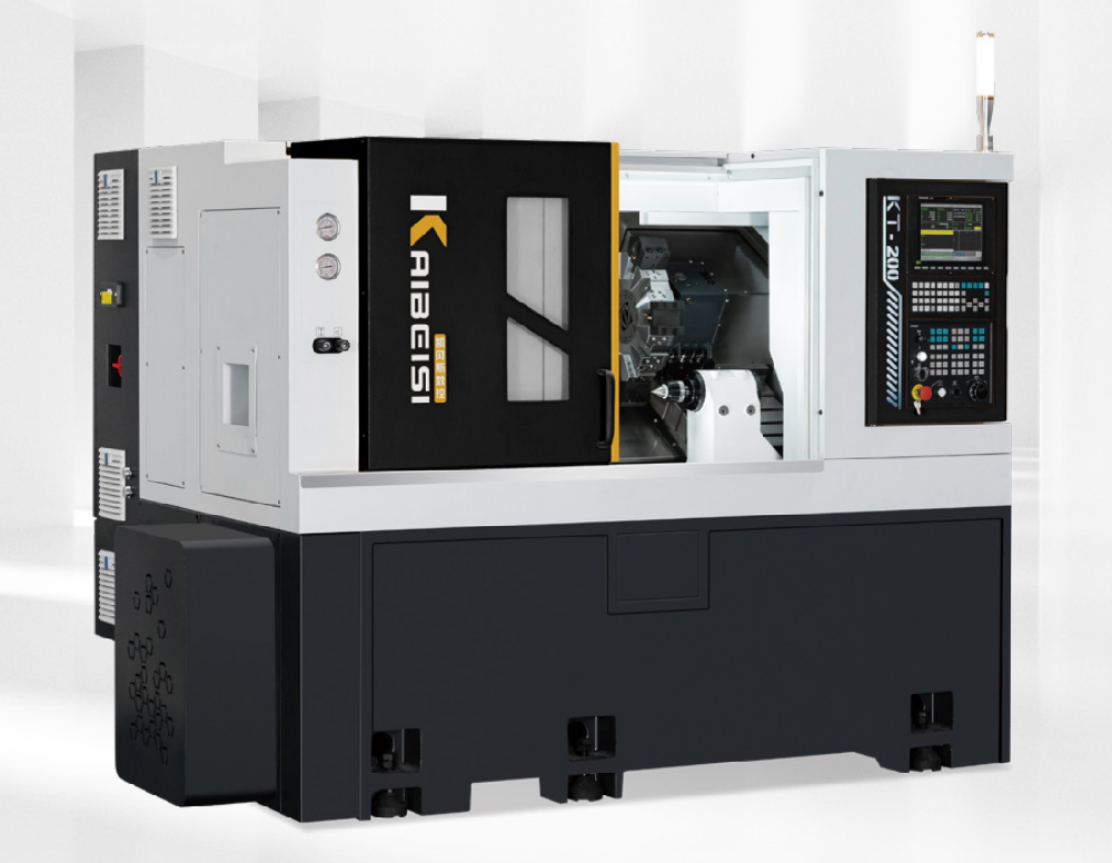
KT200 has X/Z travels of 205/530 mm and lists 25 m/min rapid movement. Its programmable tailstock should be assessed against the actual part length and center requirements, including approach clearance for turning and drilling tools.
Three different diameters
- Usable bar alternatives
- 51 or 65 mm
- Spindle through-hole alternatives
- 52 or 66 mm
- Bed swing
- 500 mm
A spindle bore is not usable bar capacity, and bed swing is not turning diameter. Match the spindle, drawtube, chuck/collet and feeder before selecting stock. Obtain the exact 51 or 65 mm package in writing.
The KT page also covers KT300, whose larger chuck, spindle nose, motor and bar figures belong to a different column. The 74 mm bar capacity and 15 kW spindle listed there are not KT200 upgrades unless a separately identified configuration is offered.
KT200's 12-position turret lists 25 × 25 mm external tool shanks and a 32 mm boring-bar holder diameter. Submit the full tool list, especially long internal tools and tools near the tailstock. Tool-station count is separate from the number of operations that can be completed without interference.
K46DM: map every cross feature to a tool
Review K46DM model specifications ↗
K46DM combines turning with a direct Y-axis arrangement. Its product description lists 100 mm Y travel and four-axis simultaneous milling capability. X/Z travels are 205/380 mm; the reviewed table specifies a 45 mm bar capacity and a 46 mm spindle through-hole.
For an off-center hole, slot, flat or end feature, identify the driven holder orientation and approach direction. Confirm C-axis functions, clamping/indexing, interpolation, tool reach and the CAM/postprocessor for the ordered control. A Y-travel number alone does not prove a complete one-setup process.
Choose one turret interface
15-position BMT45 or the 12-position BMT55 option. The interfaces and tooling packages are alternatives; they are not a combined 27-position magazine. Specify driven holders, permitted tool projection and the required torque/speed duty.
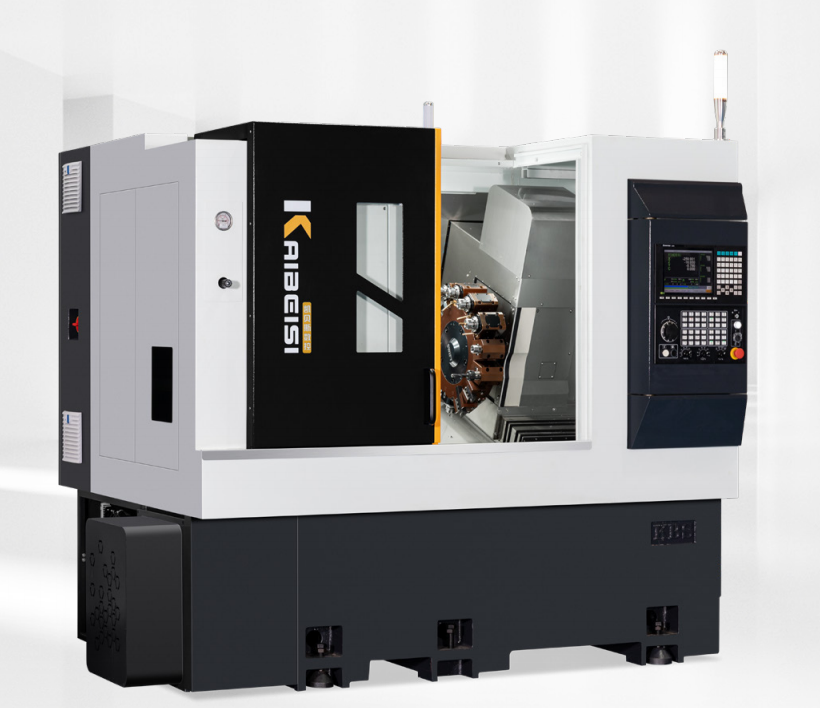
The K46DM parameter table lists a 3.1 kW driven-tool motor. This is distinct from its 7.5 kW main spindle and from the larger models' spindle ratings. Confirm the driven-tool performance for the cutter/material and required milling operation.
A programmable tailstock, part catcher and robot are described as optional equipment. Plan their clearance with the driven tools and fixtures. They require individual scope, interfaces and commissioning arrangements; an optional robot is not a completed automated cell.
Make the quotation identify a complete machine
Spindle and workholding
Name the spindle nose, speed/torque schedule, usable bar path, chuck/collet, jaws, drawtube and feeder interface. For supported parts, add tailstock travel, center and force arrangement with the actual setup drawing.
Tools and controller
Name turret interface/stations, every driven holder and tool shank, control make/model, licensed functions, CAM/postprocessor and programming support. A photographed controller is not an equipment schedule.
Peripheral equipment
Include coolant/chip handling, feeder, catcher or robot where required, together with safety interfaces, installation and operator access. KT200 lists a 2500 × 1700 × 1800 mm machine envelope and 4200 kg; use the final configured layout for the site.
The current direct-Y page heading names K46DM/K52DM/K66DM, while the attached parameter table labels its third column K75DM. This study uses the unambiguous K46DM column. If comparing a larger model, obtain a named current specification rather than transferring numbers between the heading and table.
Prove the complete part after unclamping
For supported turning
Use the actual material, blank and jaw/center arrangement. Inspect diameters, runout, taper, shoulders and surface finish, including changes between supported and unsupported operations. Record any repositioning and how the datum is preserved.
For turning–milling
Run the complete tool sequence with the proposed holders. Measure cross-feature positions relative to the turned datum, inspect milled/ drilled features and check interference at each tool change. Include any rear-face work or second clamping in the demonstration.
For production planning
Time loading, clamping, turning, milling, tool changes, part release and unloading. Record rejects and setup changes across the agreed batch mix. The catalog's X/Z repeat-positioning figure is not a finished-part tolerance or a production-rate guarantee.
Keep the program, tooling, inspection method and measured sample results with the acceptance record. Specify operator training, spare/consumable supply, fault diagnosis and responsibility for feeder/robot support in the purchase proposal.
Keybase's metal-cutting equipment scope
Guangdong Keybase CNC Equipment develops and manufactures CNC lathes, turning–milling equipment, robotic handling and customized dedicated machines. Its official company material describes development, production and application support, and shows machine-component machining and assembly facilities.
A published invention application, CN117102896A, names 广东凯贝斯数控设备有限公司 as applicant. Filed 23 October 2023 and published 24 November 2023, it concerns a turret-machine arrangement with a tailstock slide and replaceable tailstock/power-head assembly. This is a dated technical publication, not a granted-patent status claim or confirmation that either reviewed model implements every described element.
The two models above cover different part requirements within a wider lathe catalog. Supplier statements about component-making equipment do not replace serial-number inspection and an agreed production-part trial. The selection guidance here is CNCVerified's analysis of the reviewed material.
Send a part and tooling brief
Attach blank/finished-part drawings, material, bar diameter, part length, clamping/support plan, cross features and tolerances. Include batch mix, automation needs, preferred control and destination utilities. Request one identified spindle, turret and service package.
Request a Keybase quote ↗