

广东圣特斯数控设备有限公司
Foshan, Guangdong
STS: build the tool route for a bar-fed turned part
Compare H46 gang tools with HXY46 cross-feature heads. Both accept 45 mm bar, but their cutting envelopes and options differ.
Official H / HXY tables and company history reviewed 8 October 2026
Turn the part drawing into an operation list
Turned surfaces and axial holes
List facing, external diameters, shoulders, internal bores and cutoff. Identify the stock, jaw/collet projection and each tool's approach. Compare the H46 gang-tool arrangement against the actual sequence.
Cross holes, flats or slots
Add tool orientation and the datum relationship for each feature. HXY46 offers a Y-axis arrangement and alternative driven heads; specify the head, holder and spindle-indexing functions needed for the feature rather than ordering a Y axis alone.
Back-face work or handling
Show operations after cutoff and how the part will be held again. Neither reviewed model table establishes a complete sub-spindle transfer solution. Name any second operation and the equipment or cell that performs it.
Send this operation list with the finished-part and blank drawings. It gives the supplier a concrete tool/fixture brief and exposes the steps that remain outside the proposed machine.
Check the part, jaws and tool positions together
| Envelope or interface | H46 | HXY46 |
|---|---|---|
| Maximum swing / turning diameter | 400 / 320 mm | 160 / 150 mm |
| X entry, diameter programming | 800 mm | 800 mm |
| Z travel | 250 mm | 250 mm |
| HXY Y travel | Confirm the offered H setup | 200 mm |
| Bar capacity / spindle bore | 45 / 56 mm | 45 / 56 mm |
| Spindle nose / nominal chuck | A2-5 / 6 inch | A2-5 / 6 inch |
| Maximum spindle speed / motor | 4000 rpm / 5.5 kW | 4000 rpm / 5.5 kW |
Swipe to compare the models on a narrow phone.
A 56 mm spindle bore does not increase the stated 45 mm usable bar capacity. A 6-inch chuck does not guarantee clearance for a 150 or 320 mm finished part with every jaw and tool. Request the actual clamping and tool-position drawing, including the longest internal tool and cross-feature holders.
The shared H table also includes Y and tailstock entries whose configuration is not clearly tied to the offered short-travel setup. Confirm any such equipment and its usable space explicitly. Do not transfer a shared tailstock number into a promised supported-part length.
H46: lay out the gang tools before adding options
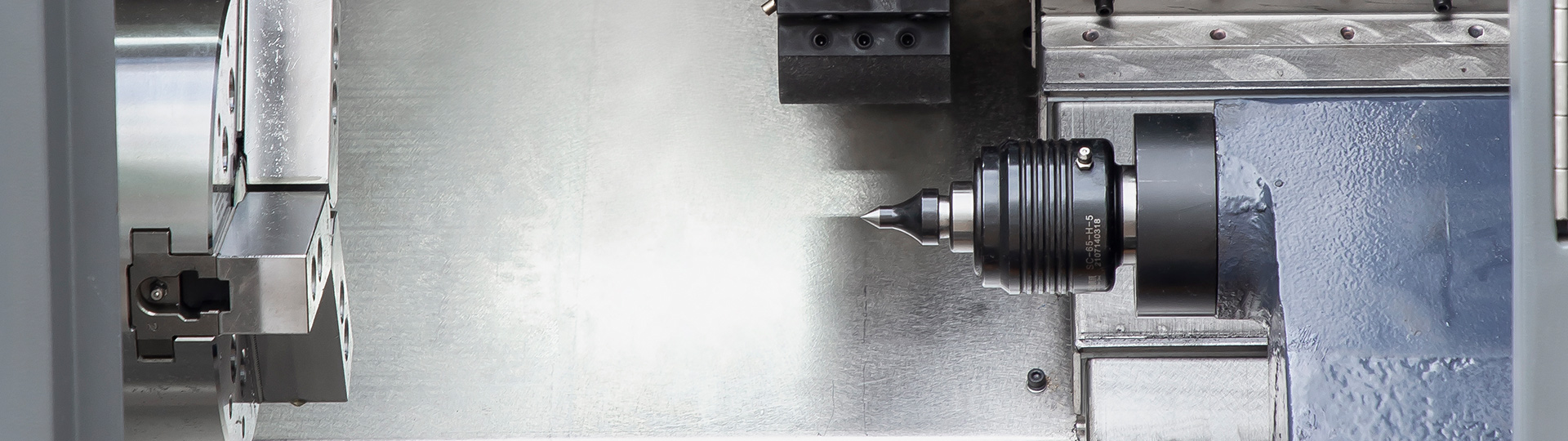
The H-series description identifies a T-shaped gang-tool plate and 30° cast slant bed. Arrange tools in operation order, with approach/retract moves and clearances between adjacent holders. A gang-tool layout can require a different program and reach assessment from a turret package.
The option table marks a turret and driven-head equipment as optional. Obtain the selected station count or head arrangement, its interface and its cutting duty. A turret photographed or available in the wider catalog is not automatically part of H46.
Syntec control and a sleeve-type mechanical spindle are marked standard; FANUC and an electric spindle are optional. The table distinguishes H46's 5.5 kW spindle motor from a 7.5 kW drive-power entry. Require the delivered control, spindle and duty schedule to be named together.
The page offers a lengthened version adding 80 mm Z travel, with changes to machine dimensions and weight. Treat it as a separately identified order configuration, not an increase already included in the 250 mm Z-travel model.
HXY46: assign the driven head to each cross feature
Side or end approach
The manufacturer lists side, end-face and other driven-head alternatives. Identify the required tool direction for every hole, slot or flat, then request holder reach, power/speed duty and clearance with the jaws and neighboring tools.
Positioning and clamping
The option table marks hydraulic spindle braking standard. Confirm the spindle orientation/indexing, braking and interpolation functions for the proposed control and operation. A brake or Y-travel figure alone does not demonstrate every milling process.
What the option table excludes
The reviewed HXY table marks a turret and the listed automation manipulator unavailable. It does offer selected feeding, catching and chip-handling accessories. Do not carry H-series or company-wide robot options into HXY46 without a separately documented solution.
Build the cycle from the selected heads, tool approaches and part handling. Include orientation and brake-release steps; a spindle brake should not be treated as proof of continuous C-axis contouring or synchronous tapping.
Make the stock-to-part sequence explicit
Feed and clamp
Choose the chuck or front-push/rear-pull collet package, drawtube and feeding arrangement. Confirm permitted stock condition, guidance, remnant handling and interlocks. The nominal chuck entry does not replace an identified workholding schedule.
Cut and collect
Demonstrate cutoff, part retention and release into the selected catcher or downstream fixture. Check vulnerable surfaces, orientation and chip interference, especially when driven-head operations precede separation.
Recover and restart
Demonstrate safe recovery after a feed, tool or part-release interruption. Record how an unfinished part is identified and how the operator prevents a duplicate or skipped operation. Specify feeder/catcher support and commissioning responsibilities.
Prove the complete part with the quoted tools
Run the actual material, stock diameter, jaws/collet and complete tool sequence. For H46, inspect turned diameters, shoulders, internal features and cutoff condition. For HXY46, also measure cross-feature positions against the turned datum and check the milled or drilled surfaces after unclamping.
Agree on tolerances, surface requirements, measuring equipment and the sample/batch method. Record setup, feeding, cutting, tool moves, cutoff and collection separately; include second-operation work and rejected parts. Do not turn a catalog axis figure into a finished-part accuracy or output guarantee.
Request the final installation layout and utility schedule. The base tables list H46 at 2230 × 1560 × 1770 mm and 2400 kg, and HXY46 at 2100 × 1520 × 1940 mm and 2600 kg. Allow extra space and loads for the ordered feeder, chip equipment and access. Include control licenses, program backups, tool/fixture drawings, training and destination service in handover.
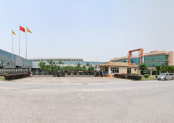
STS's turning and application-engineering scope
Guangdong Shengtesi CNC Equipment, branded STS and identified as 广东圣特斯数控设备有限公司, develops CNC lathes, turning–milling equipment, automation and customized dedicated machines in Foshan. Its official history traces the business to a Foshan company established in 2002 and names the Guangdong company name from 2017.
A Guangdong 2023 engineering-research-center assessment list records the company's high-efficiency precision automatic CNC equipment center at entry 469 with a passing assessment. This is a dated engineering-center record, not certification of either reviewed machine or a current independent factory audit.
The selection route here reflects the two model-specific tables. Company-wide automation capabilities and historical quality-system statements do not define the equipment, service scope or acceptance criteria of a particular H46/HXY46 order.
Send the part and tool route
Attach finished-part and blank drawings, material, bar size, operation sequence, cross features and tolerances. Include tooling/workholding, any second operation, feed/catch needs, batch mix and destination utilities.
Send STS RFQ ↗