

昆明拓思数控机床有限公司
Kunming, Yunnan
Tuosi boring mills: plan the housing, its rotation and bore reach
Choose between TS110T1 and TS110T4 using the loaded fixture, then prove how the boring spindle reaches the critical holes without losing their datum relationships.
Official company introduction, two complete model descriptions and government record reviewed 8 October 2026
Five motion axes do different jobs
Tuosi's T-series descriptions define X as transverse table movement, Y as vertical spindle-head movement, Z as longitudinal table movement, B as table rotation and W as axial boring-spindle movement. A long hole, an opposite face and an offset bore need different combinations of those motions.
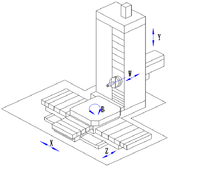
- X / Y
- Locate the bore across the face and at its height. Include fixture height, tool length and clearance from the housing's adjacent walls.
- Z / W
- Z positions the table longitudinally; W extends the boring spindle. Both models list 600 mm W travel. That does not establish a 600 mm usable boring depth with every tool and housing.
- B
- Rotate the loaded table to present another face. Check the swept outline of the part and fixture, its center of gravity, tool withdrawal and clamp state throughout the rotation.
The manufacturer describes Siemens 828D with six-axis control and four-axis simultaneous movement; its function list distinguishes five feed axes from the spindle. Request the actual enabled interpolation and postprocessor. The number of controlled axes is not evidence of simultaneous five-axis contour cutting.
Compare the loaded table before the travel numbers
TS110T4 provides a larger table, greater listed load and more X/Y travel than TS110T1. Both use a 110 mm boring spindle, 600 mm W travel and a 210 mm milling-spindle end dimension. The larger machine does not automatically solve a hole that requires a longer unsupported boring tool.
| Selection check | TS110T1 | TS110T4 |
|---|---|---|
| Table surface | 1000 × 900 mm | 1200 × 1400 mm |
| Listed maximum table load | 2500 kg | 6000 kg |
| X / Y / Z travel | 1000 / 900 / 1000 mm | 1600 / 1600 / 1200 mm |
| W spindle travel | 600 mm | 600 mm |
| B rotation | Any-angle 360° positioning | Any-angle 360° positioning |
| Spindle-speed range | 10–1500 rpm | 10–2000 rpm |
| Spindle motor entry | 17.5 kW | 19.5 kW |
| Listed spindle torque | 1500 N·m | 2000 N·m |
| X/Y/Z rapid movement | 10,000 mm/min · 10 m/min | 10,000 mm/min · 10 m/min |
| Listed machine mass | 12,500 kg | 28,500 kg |
| Existing model reference | TS110T1 details ↗ | TS110T4 details ↗ |
Swipe to compare the two table sizes and axis travels.
Use the combined mass of casting, fixture, clamps and attachments. Ask for the permissible load distribution and eccentric load at the intended B positions. A housing that fits the table face can still collide during rotation, exceed an allowable overturning moment or prevent the spindle reaching a low bore.
The wider catalogue names T, P and PR families. These two existing records cover the reviewed T-series references; a floor-type or other family should be evaluated with its own foundation, axis definitions and technical sheet.
Make the boring setup describe the weakest reach
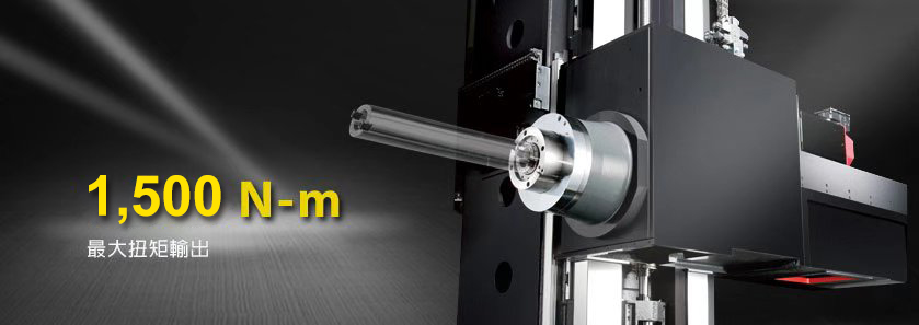
A deep housing bore may require spindle extension, tool overhang or both. Identify the diameter, depth, material and interruption in the cut; show the supported and unsupported lengths. Have the proposed combination demonstrated at the longest reach and at the selected gear/speed, rather than accepting a short, open-face demonstration.
Boring versus face milling
The descriptions distinguish the boring and milling spindles and a servo drive with two mechanical speed stages. T1 lists separate boring-spindle and milling-spindle torque entries; do not transfer either to T4 or treat maximum torque as available at maximum rpm. Obtain the supplied torque/power curves and demonstrate the actual heavy cut.
Toolholder and pull stud
Both tables specify ISO 50 7:24 taper, MAS BT50 shank and LDA-50 pull stud. Match the actual holder, retention knob and any extension or angle head to the delivered spindle. A BT50 label alone does not establish compatibility with every existing tool assembly.
Attachments and tool changes
Tuosi describes machining with compatible attachments, but the reviewed pages do not establish an automatic tool-magazine capacity or a complete optional-head package. List each head, holder, support, probe and tool-change method in the quotation; prove access to the difficult face with that exact assembly.
Prove the relationship between holes on different faces
The manufacturer's model descriptions specify linear scales on X/Y/Z, an encoder on B and semi-closed-loop position detection on W. Those arrangements describe feedback, not the tolerance of a released housing at a particular reach or temperature. The accuracy rows combine linear values and arcseconds without an unambiguous axis-by-axis mapping; obtain the original agreed inspection schedule instead of turning them into one part-accuracy number.
Freeze the locating plan
Mark the casting supports, clamp positions, reference faces, allowance and tool access. Identify which dimensions must remain related through B rotations and which operations would require reclamping.
Cut at the difficult conditions
Use the intended material, boring length, tool overhang, fixture load and speed/gear. Include opposed or adjacent-face bores, an interrupted cut where relevant, and the agreed face-milling operation. Record warm-up, coolant and offsets.
Measure the released housing
Check bore diameter and form, bore-to-bore position or coaxiality, face relationships and the specified surface condition against the drawing datums. Include the part before and after clamp release where distortion matters. Agree the instrument, uncertainty and temperature conditions.
Repeat the complete route
Repeat loading, datum setting, B rotation, tool changes and inspection. Record accepted output and recovery after a stop. Rapid movement and a successful single bore do not establish the complete housing cycle.
Connect the machine build to its installation records
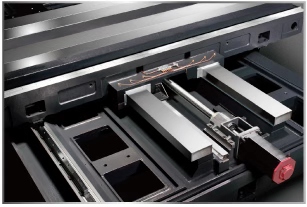
Kunming Tuosi's company introduction describes machining large components on boring/milling and five-face equipment and a guideway grinder, outsourcing coordinate measurement of smaller components, then carrying out geometry checks, trial cutting and laser positioning checks on assembled machines. Ask for the records for the machine being supplied, including which measurements were performed externally.
The Jiangchuan industrial-park authority's 2021 annual-account disclosure, published in September 2022, names 昆明拓思数控机床有限公司 among four enterprises with signed park-entry agreements. This is a historical identity/project record; it does not establish today's production address, machine output or certification.
- Foundation and access
- Obtain the delivered machine outline and foundation drawing, floor loading, utility demand and assembly/lifting method. Include the moving table envelope, full B sweep, chip collection and maintenance access; machine mass is not a foundation design.
- Configuration freeze
- T4's component list expressly permits substitutions in special circumstances such as long delivery times. Record the actual spindle, guideways, scales, drives and control software, and require approval of substitutions that change the accepted capability.
- Documents and recovery
- The official pages list mechanical/hydraulic manuals, precision inspection records, packing list and electrical documentation. Include foundation and circuit drawings, parameter/program backups, lubrication instructions and a demonstrated restart/referencing procedure in the handover.
Send the housing drawing and its loaded-fixture sketch
Include material, blank/final dimensions and combined load; bore diameters, depths and cross-face datums; fixture outline and B swept envelope; proposed W extension/tool overhang; attachment and toolholder requirements; trial/inspection limits; batch and cycle target; destination and foundation constraints. Identify T1 or T4 and the exact controller/configuration requested.
Send Tuosi RFQ ↗