

WEINO · 威诺
Putian, Fujian
WEINO: plan multi-face machining around a stable datum
Map the faces, bores and locating surfaces of your large component. Then choose a moving-column or three-face gantry arrangement that can reach them with the part held as intended.
Official company, model tables and LF technical PDF reviewed 8 October 2026
Draw the machining plan before counting heads
Establish the reference
Mark the surfaces supporting and locating the blank. Identify which datums exist on arrival and which are created during machining.
Assign each feature
Mark every bore, milled face and tool approach. Include fixture obstructions and clearance for tool entry, cutting and withdrawal.
Keep the geometry
Name the dimensions connecting opposite faces, bore axes and datum surfaces. Decide how they will be measured after release from the fixture.
Keeping a part in one locating setup can reduce datum transfers, but does not by itself prove finished-part accuracy. The proposed head arrangement, fixture stiffness, calibration, cutting sequence and inspection method must support the drawing.
WN-DB2511Z: moving-column boring and milling
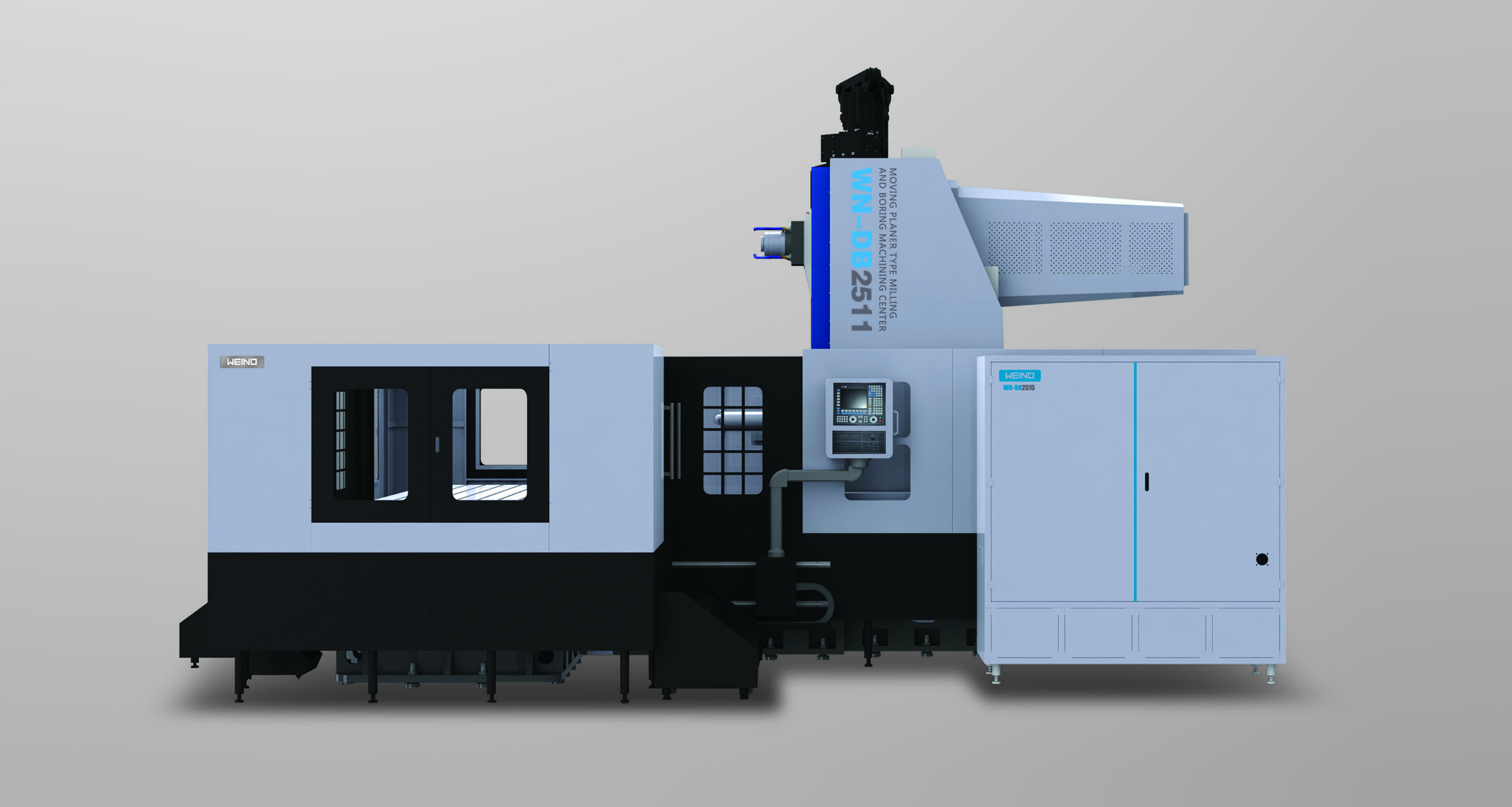
Published base envelope
- Table / listed load
- 2500 × 1600 mm / 10000 kg
- X / Y / Z travel
- 2560 / 1100 / 600 mm
- Spindle interface / maximum speed
- BT50 / 6000 rpm
- Magazine / tool-to-tool change
- 32-tool chain / 32 seconds
- Spindle motor entry
- 22 / 26 kW; duty not defined in this model table
Keep the model suffix
The DB catalog separately lists WN-DB2511Z×2 as a two-sided version. A photograph or family description does not make that arrangement part of the WN-DB2511Z quotation. Identify the head count, approach directions and exact configuration in the proposal.
Table dimensions are not the accessible machining envelope. Check each feature with the blank, fixture, tool length and approach direction included. Agree how the 10000 kg rating applies to the combined workpiece and fixture and its load distribution.
The current table leaves control and accuracy fields blank. Its rapid-feed row contains four values under a three-axis heading, so no axis mapping is inferred here. Request a named controller, axis diagram and model-specific inspection specification.
WN-LF4015Z×3: organize three-face cutting
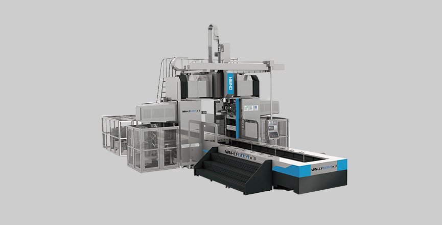
LF4015Z×3 configuration
- Table / listed load
- 4200 × 1200 mm / 10000 kg
- Main X / Y / Z travel
- 4000 / 2000 / 1000 mm
- Spindle interface / maximum speed
- BT50 / 6000 rpm
- Spindle power duty in the PDF
- 22 kW continuous / 26 kW for 30 minutes
- Published tool-to-tool time
- Horizontal 32 seconds / vertical 2.5 seconds
Ask for a head-by-head operation sheet
Assign the top and side features, tools, datum offsets and cutting sequence. Request sections showing spindle approach, side-head clearances and the supported blank width/height with your fixture in place. Main XYZ travel alone does not establish access for every head.
The horizontal and vertical tool-change times describe different tool systems. Neither represents the finished-part cycle. Include head movements, approach/retraction, probing, chip removal, loading and inspection in the proposed time study.
The online table and technical PDF contain multi-value speed and accuracy rows without a complete one-to-one axis mapping. Obtain the current axis-specific sheet and test method rather than assigning these numbers to whichever head appears in the image.
Demonstrate the relationships that matter on the part
Before cutting
Approve the incoming blank condition, locating scheme, clamping force, tool list and datum-setting method. Record head geometry/calibration and the agreed machine warm-up state. Use representative material and the difficult features of the actual drawing.
Across the heads
Machine and inspect features whose relationships cross the selected head directions. Examples may include opposite-face spacing, perpendicular faces or related bores, where required by your drawing. Check accessible features and difficult tool projections, not only an easy demonstration face.
After release
Measure the finished component against its drawing datums after unclamping under the agreed inspection procedure. Where thermal state affects acceptance, define the stabilization conditions. Keep reports tied to the program, tool list, fixture and drawing revision.
Separate positioning/repeatability specifications from finished-part tolerances. A machine-axis figure does not include all effects of tooling, material, cutting, clamping and measurement. Request the inspection equipment, uncertainty and method suitable for the required relationships.
A machining center is one part of a production system
WEINO's company material also describes intelligent-manufacturing factory solutions. If the quotation extends beyond a standalone machine, draw a clear boundary around what is supplied and who accepts each interface.
| Interface | Specify in the order |
|---|---|
| Part handling | Blank and finished-part states, lifting/loading, fixture transfer, orientation and safe recovery |
| Programs and production data | File formats, revision control, part identification, approved editing and data-exchange responsibilities |
| Tooling and chip/coolant equipment | Supplied holders/cutters, tool measurement, chip route, filtration and maintenance access |
| Site and support | Complete installation layout, utilities, foundation, control backups, training, spares and destination service |
Swipe the interface brief on a narrow phone.
Agree machine acceptance and integrated-line acceptance separately. Test stoppage and restart, changed drawings, rejected parts and operator access alongside normal production. Marketing descriptions of an automated factory do not establish the performance of your proposed cell.
WEINO's company and product focus
The official material identifies 福建省威诺数控有限公司 in Putian, Fujian. It describes compound gantry equipment, vertical machining centers, five-axis machines, turning equipment and manufacturing-system solutions, with an emphasis on machining symmetrical components.
A Fujian industry department notice published 22 February 2022 includes the company's industrial design center in the ninth provincial recognition list. This is a dated company-level record, not certification of either reviewed machine or a guarantee of your machining result.
The face-map, datum and acceptance guidance above is CNCVerified's editorial analysis. Ask the proposal to identify the legal seller, exact model suffix, heads, controls, tooling, installation and service obligations.
Prepare a multi-face component brief
Attach the blank and finished-part drawings, marked datums and machined faces, material, fixture concept and combined mass. Include the cross-face tolerances, batch mix, inspection method and standalone-machine or integrated-line scope.
Send WEINO RFQ ↗