

南阳市中捷数控科技有限公司
Nanyang, Henan · deep-hole drilling
Zonjet: match the bore to its support and coolant system
Compare ZJZ500 shaft drilling with ZJD20-1612 BTA drilling. The overlapping diameter range does not make their workholding, depth or installation needs interchangeable.
Official company and both model tables reviewed 8 October 2026
The hole drawing comes before the machine size
Specify hole diameter, effective depth, blind/through condition, entry surface and any intersecting holes. Add the blank's overall dimensions, material and heat-treatment state. A quoted maximum drilling depth is separate from the length of stock that can be clamped, supported and approached by the tool.
| Planning question | ZJZ500 | ZJD20-1612 |
|---|---|---|
| Reviewed application | Rod/shaft deep-hole drilling | Larger-bore BTA drilling |
| Published hole diameter | 4–30 mm | 20–120 mm, BTA |
| Maximum drilling depth | 500 mm | 2000 mm, BTA |
| Workpiece support entry | Maximum workpiece length 600 mm | 1800 × 1500 mm table; 15-ton load |
| Maximum spindle speed | 4500 rpm | 1000 rpm |
| Spindle motor | 15 kW | 30 kW rated; 37 kW for 30 minutes |
| Coolant pressure / maximum flow | 100 kgf/cm² maximum / 80 L/min | 30 kgf/cm² rated / 345 L/min maximum |
Swipe to compare both drilling systems on a small phone.
Between 20 and 30 mm, both published ranges include the diameter. Choose with a toolmaker-reviewed process and an actual part trial: stock shape, depth, entry support, chip route and material can matter more than diameter alone. The tables do not establish that every maximum diameter, depth and removal rate can be achieved together.
ZJZ500: define the shaft support and spindle package
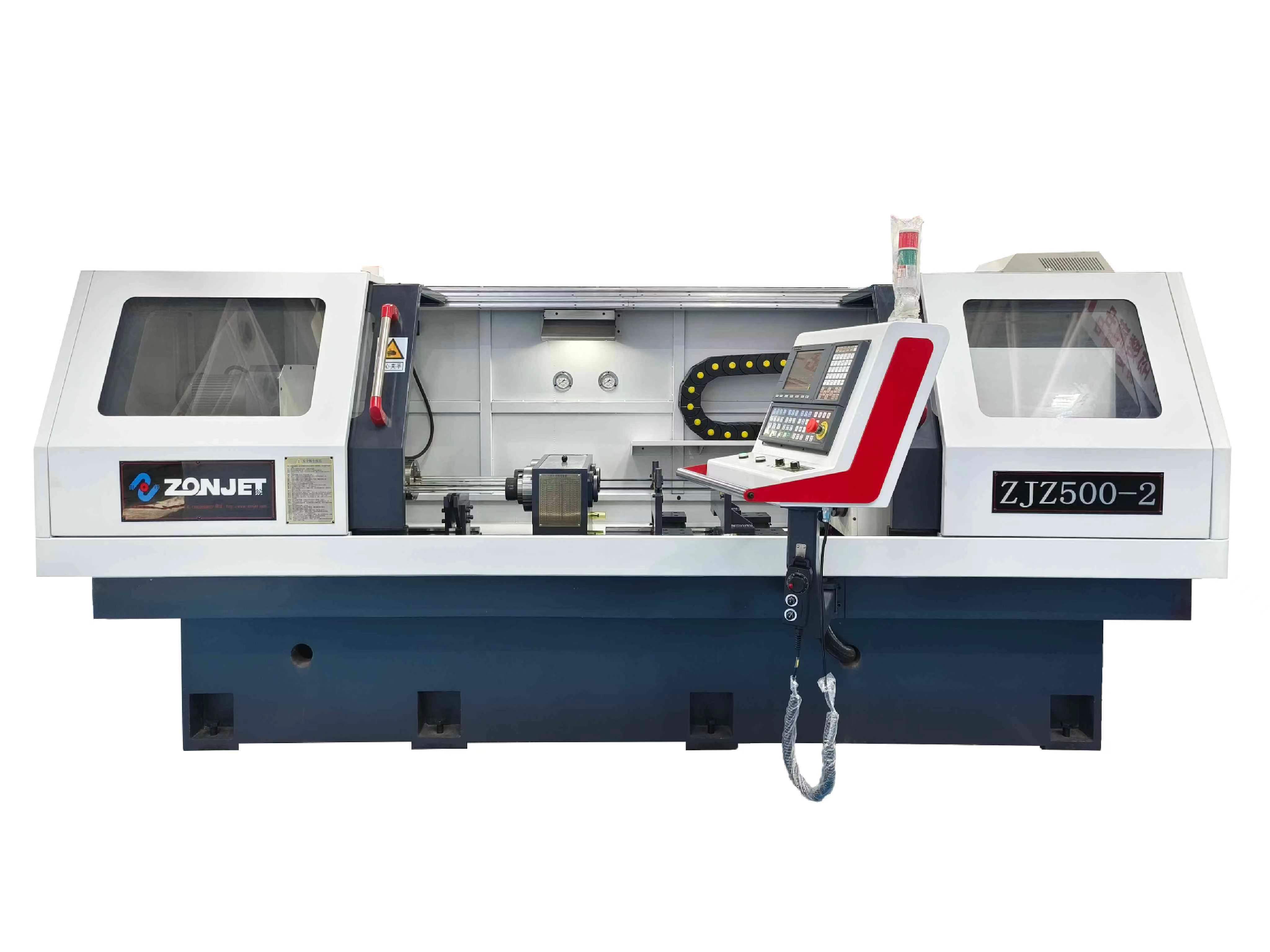
Clamping and entry
The series description offers a three-jaw chuck or a self-driving push-disc arrangement. Name the chosen fixture, shaft support and entry guide, then demonstrate alignment with the actual blank. Supply end geometry, runout requirements and the datum used to inspect bore position.
Parallel work
The table gives a 200 mm spindle-center distance and optional two/three spindles; the series prose instead mentions single, double and four-spindle machines. Specify the exact offered ZJZ500 variant, spindle count, center spacing and independent functions rather than combining these statements.
Review ZJZ500 model specifications ↗
The feed range is 0–3000 mm/min; rapid traverse is 3800 mm/min, or 3.8 m/min. Neither is a recommended cutting feed for a particular tool. The text mentions Ø3 mm stainless-steel work, but the ZJZ500 table starts at Ø4 mm; a 3 mm job therefore needs an explicitly identified configuration and trial.
ZJD20-1612: check the complete heavy-workpiece arrangement
The BTA model lists X/Y/Z travels of 1600/1200/2000 mm. Its 1800 mm table dimension is identified as the drilling direction. Submit the supported blank, fixture and hole-entry arrangement together; table length is not a guarantee that the entire 2000 mm bore is available with every setup.
Plan the pressure-head connection, tooling and chip-return circuit with the supplier. The 30 kW rated spindle and 37 kW 30-minute overload are different duty conditions. Obtain the speed/torque and duty schedule for the proposed bore instead of using overload power as continuous capacity.
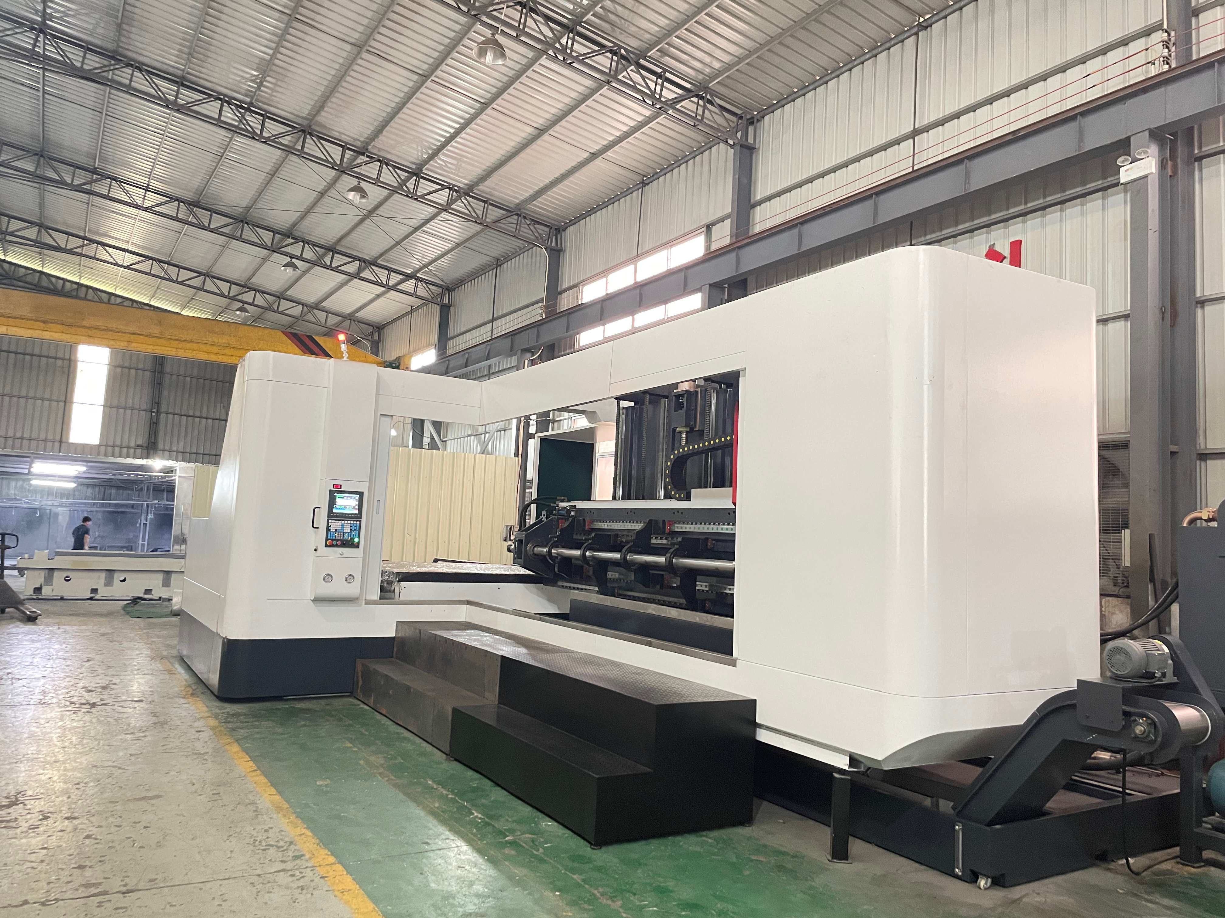
Allow for the catalog's approximately 38-ton machine, 10300 × 5000 mm footprint and 3800 mm height, then add lifting routes, working access and peripheral equipment from the final installation drawing. The 15-ton table load and machine mass describe different loads.
Two rows in the online table have mismatched labels/units: a spindle-feed row shows “22 mm” and a T-slot row shows “0–3000 mm.” This page does not reinterpret them as a feed range or slot width. Request a corrected, signed specification for those details before finalizing tooling and fixtures.
Buy a coolant circuit that supports the proposed tool
Pressure at the tool
ZJZ500 quotes maximum pressure as 100 kg/cm²; ZJD20-1612 quotes 30 kg/cm² rated. Here these are expressed as kgf/cm². Confirm the engineering units, measurement location and pump performance at the required operating flow.
Flow and return
The maximum-flow entries are 80 and 345 L/min respectively. They are not proof that maximum flow and pressure occur simultaneously. Obtain a configured pump/circuit schedule and demonstrate delivery, return and chip handling on the agreed bore.
Fluid service
Specify compatible cutting fluid, filtration, tank capacity, temperature control and maintenance access. Identify alarms and the permitted response to pressure/flow loss, abnormal chips or a stopped tool. Include cleaning, filter changes and restart in training.
Coolant ratings support process selection; they do not guarantee straightness, finish or tool life. Retain the actual fluid settings and chip observations with the trial report.
Inspect the bore beyond its entrance
Agree on the sample
Use the actual material condition, bore geometry and fixture. Name tooling, entry preparation, coolant settings and any intersecting-hole features. For a multi-spindle order, demonstrate the proposed simultaneous operation rather than timing one spindle and multiplying its output.
Agree on measurements
Define diameter, bore-position/straightness requirements, roughness locations and the inspection method before the trial. An acceptable entrance measurement alone does not establish the deep internal result. Where direct access is limited, agree on a suitable inspection or sacrificial sample approach.
Measure the production sequence
Record loading, alignment, drilling, tool withdrawal, chip clearing and unloading. Include inspection, tool changes and recovery where relevant. Confirm acceptance after release from the fixture and retain the sample, settings and measurement report.
For the quotation, separate machine, tools, workholding, coolant peripherals, installation, operator/process training and maintenance responsibilities. Ask how overseas support and replacement parts will be delivered for the destination; a domestic service-network statement is not an agreed international service level.
Zonjet's deep-hole drilling manufacturing scope
Nanyang Zonjet CNC Technology, identified in its official material as 南阳市中捷数控科技有限公司, develops deep-hole drilling equipment. Its catalog includes shaft machines, multi-axis drilling/drilling–milling equipment and customized drilling systems. The company describes its own casting, heat-treatment, component-machining, finishing and assembly chain; those are manufacturer statements about production scope.
The Henan 2025 second-batch technology-based SME list names the exact company at entry 2161. It provides a dated company record, not model-performance certification, a current independent factory audit or confirmation of each manufacturing site.
The two machines reviewed here represent distinct bore-planning routes within the wider catalog. CNCVerified's comparison and acceptance questions are editorial guidance based on the model-specific published material.
Send a complete bore brief
Attach the blank and hole drawings, material/heat treatment, diameter, depth, entry/intersection geometry, dimensional and surface requirements, batch mix and inspection method. Add fixture/support needs, required spindle count and destination utilities.
Request a Zonjet quote ↗