

阿帕斯数控机床制造(上海)有限公司
Shanghai Lingang
APLOS: match the spindle duty to the cut, then prove the contour.
The FGV range combines a fixed-beam gantry arrangement with direct-drive axis technology. Compare the basic FGV1060 envelope, the FGV1060A direct-coupled spindle and the FGV1280A geared spindle against the actual cutter, fixture and finished surface.
Company, FGV family and two dedicated A-model pages reviewed 8 October 2026
One mould can require two very different cutting duties
Small-tool contour finishing
Send the smallest tool, holder projection, tightest curvature, surface requirement and program segment. The direct-coupled FGV1060A spindle references are 12000/15000 rpm alternatives. Examine motion through corners and changes in curvature with the actual CAM/postprocessor and controller settings.
Larger-tool removal
Send material condition, cutter diameter, engagement, reach and fixture. FGV1280A describes a reduction-gear spindle with 6000 rpm maximum speed and BT50 tooling. Require the speed/torque curve and cutting trial for the selected gear range, rather than choosing from a headline torque value.
Define roughing, semi-finishing and finishing as a complete process, including tool changes and inspection. A fast axis traverse is not cutting speed, and either is different from accepted-part output.
Keep the family and A-model references separate
| Reference | FGV1060 family listing | FGV1060A dedicated listing | FGV1280A dedicated listing |
|---|---|---|---|
| Working travel | X/Y/Z: 1000 / 600 / 600 mm | Y: 600 mm; Z: 600 mm table reference. X/build to confirm below. | X/Y/Z: 1200 / 800 / 800 mm |
| Table / load | 1100 × 600 mm / 1000 kg | 1100 × 600 mm / 1000 kg | 1300 × 800 mm / 1500 kg |
| Nose to table | 100–700 mm | 100–700 mm table reference | 100–900 mm |
| Spindle route | Confirm the ordered spindle | Direct-coupled; BBT40; 12000/15000 rpm alternatives | Reduction gear; BT50; 6000 rpm maximum |
| Base machine mass | 14000 kg | 14000 kg | 18000 kg |
Swipe horizontally to read one complete model column on a narrow phone.
The FGV1060A family table gives 1000 mm X travel, while its dedicated table prints 1001 mm. Its dedicated table gives 600 mm Z travel and 100–700 mm nose-to-table space, but descriptive text also mentions an 800 mm Z build. Obtain the current build drawing before committing a fixture to those limits; the larger figure is not automatically included.
The family table's third column is labelled FGV1280B. The existing FGV1280A listing here is based on its dedicated A-model page; the B suffix and its spindle configuration are not substituted into it.
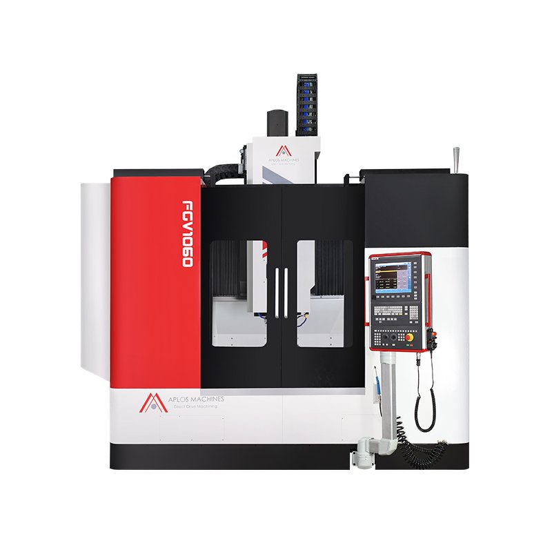
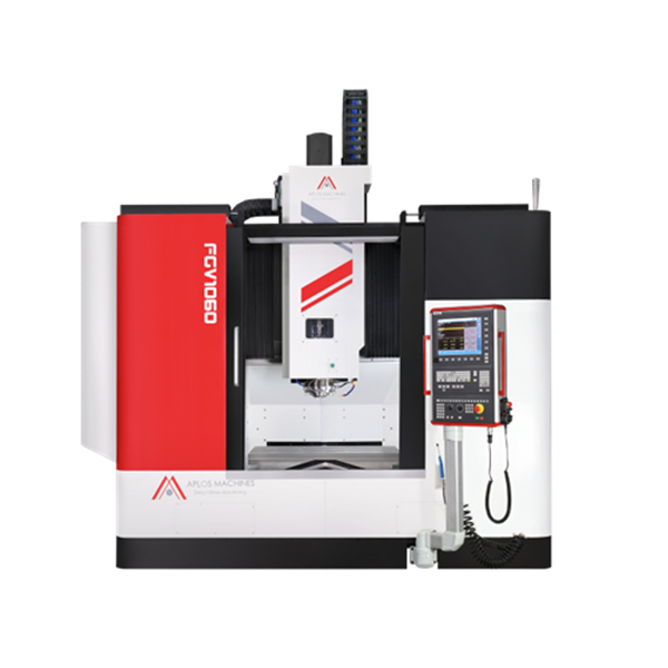
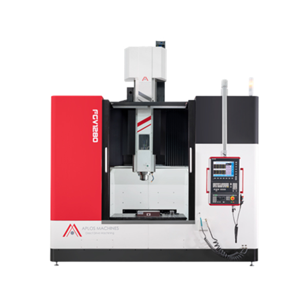
The cutter, duty and occupied tool positions form one package
FGV1060A: direct coupling and BBT40
The dedicated table gives 15 / 22 kW spindle-motor power under S1 / S6–40% duty labels, with 95.5 / 140 Nm motor-torque entries. Specify the selected 12000 or 15000 rpm build and its full torque/speed curve. Do not assume the motor's listed torque remains available at maximum spindle speed.
Its 24-position disc magazine lists tool diameter Ø80 mm with adjacent tools present or Ø150 mm with them absent, maximum length 300 mm and mass 8 kg. Include the large boring/face tool's neighbouring empty stations in the tool schedule.
FGV1280A: reduction gear and BT50
The table gives 17 / 25 kW and 162.3 / 238.7 Nm as spindle-motor entries under S1 / S6–40% labels. The description separately discusses a 1:4 reduction gearbox and low-/high-speed spindle-output torque. These are different reference points; require the actual gear range, output curve and duty at the intended cut.
The 24-position disc magazine lists Ø110 mm with adjacent tools present or Ø220 mm with them absent, maximum tool length 350 mm and mass 18 kg. Check holder projection and magazine occupancy as well as the cutting tool's diameter.
Both dedicated tables name Fagor 8060M and give G0 traverse of 60 / 60 / 30 m/min versus maximum cutting-feed references of 30 / 30 / 15 m/min. Use those exact entries rather than the broader 60–90 m/min claim in the descriptive text. Agree motion settings and the tool/fixture system around the part trial.
Test the difficult surface with the finished program
- At the tight curvature
- Use the production tool, holder and CAM/postprocessor on the most demanding contour. Define allowed form and surface error, measurement method and controller settings. Include changes in curvature and transitions; catalogue axis positioning and acceleration do not establish finished contour quality.
- At the heavy cut
- Run the intended material, engagement and cutter projection with the selected spindle duty/gear. Observe chip evacuation, tool condition and fixture response, then inspect the part after release. Include tool changes and any roughing-to-finishing datum relationship.
- Across the accepted cycle
- Repeat with the agreed warm-up and measurement conditions. Count accepted pieces with setup, roughing, finishing, chip handling, inspection and rejected work over elapsed time. Keep the program, machine settings, tool and fixture revisions with the results.
The model pages' promotional positioning text has a malformed unit and does not provide a complete test method. Set the part-specific acceptance from the drawing and demonstrated measurements; do not publish that phrase as a verified finished-part tolerance.
Plan the foundation, full enclosure and service access
The catalogue width/depth/height references are 3280 × 2350 × 4100 mm for FGV1060/FGV1060A and 3770 × 3730 × 4460 mm for FGV1280A. With base masses of 14 and 18 tonnes, obtain the actual foundation, handling and levelling requirements before comparing floor plans. Include chip equipment, access, doors, service clearances and the delivered machine configuration.
The dedicated A tables give 380 V / 50 Hz with 33 kVA for FGV1060A or 40 kVA for FGV1280A, plus 0.6 MPa / 500 L/min air. Confirm the destination supply, duty and supplied auxiliaries in the engineering schedule. Name the coolant/chip system, commissioning and inspection responsibilities alongside the foundation and utilities.
Identify the manufacturing company and ordered build
APLOS identifies the supplier as 阿帕斯数控机床制造(上海)有限公司 in Shanghai Lingang. Its company account describes direct-drive CNC machine development, design and manufacture for moulds, compressor/vacuum-pump equipment, semiconductor equipment, automotive and other manufacturing applications. A customer-industry list is not proof of the buyer's proposed machining result.
The Shanghai economic commission's 1 November 2023 proposed SME-support list names the exact company at innovation entry 39. This is a dated proposed-support record, not a final payment receipt, machine certification or an independent factory audit.
Request the signed build specification, supplier identity, controller/options, spindle curves, tool/fixture drawings, foundation and utilities, acceptance part and destination service. Include program/postprocessor backups, training, replacement components and the handover responsibilities. Route drawings and enquiries through CNCVerified.
Send the roughing cut and the hardest contour
Attach material/condition, blank and finished drawing, fixture mass and height, critical contour/surface, cutter/holder projection, roughing engagement, spindle duty/gear and tool schedule, inspection method, accepted-output target, foundation constraints and destination.
Send APLOS RFQ ↗