

浙江海德曼智能装备股份有限公司
Yuhuan, Zhejiang · CNC turning and automation
Headman: which feature forces your next setup?
Compare T55/500 turning, T55MY offset milling and T55MS two-end transfer. Choose around the feature, grip and datum.
Choose the operation ↓Build & entity records ↓
Original model & manufacturing materials; August 2026 issuer filing · reviewed 8 October 2026
Start with the feature, not the model suffix.
Headman specialises in CNC turning equipment and integrated automation. The three records below address distinct setup decisions within its T55 range. Its wider Hi multi-axis, larger T-series, vertical turning and automation catalogue requires separate workpiece and configuration review.
Turn, bore and thread a rotational profile
Start with T55/500. Check the actual workholding, bar passage and tailstock access. The reviewed base turret has eight positions; a similar “II/500 Super” name is a different reference.
Add flats, holes or other off-centre features
Review T55MY’s Y-axis live-tool route. Locate the feature and its tool approach in the quoted Y/C envelope. A powered tool alone does not prove that every offset feature is reachable.
Machine the reverse end without manual re-chucking
Review T55MS’s dual-spindle route. Prove the handover grip, synchronization and datum transfer. A second spindle does not establish Y motion or simultaneous independent-turret cutting.
Use one build sheet: the dimensions below retain the reviewed English T55/500 reference and Chinese T55MY/T55MS references. Model revision, spindle, control and workholding must be identified together in the quotation. Regional pages and similarly named upgrades are not interchangeable.
Turning / bar-fed work
T55/500: distinguish bar passage from spindle bore.
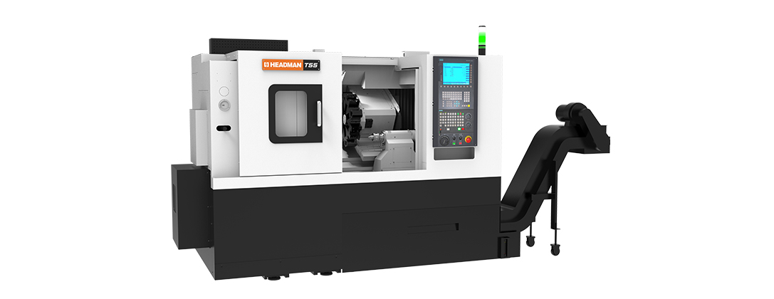
- Published cutting envelope
- 330 mm maximum diameter; 516 mm maximum length; 550 mm swing
- Bar passage / spindle bore
- 51 / 62 mm — different limits
- X / Z travel
- 190 / 561 mm
- Spindle alternatives
- Mechanical: 4000 rpm maximum; built-in motor: 5000 rpm maximum
- Power & turret
- 11 / 15 kW continuous / 30-minute; eight positions
The source explicitly separates 51 mm bar-through capacity from a 62 mm spindle bore. Specify chuck/collet, drawtube, bar shape/straightness, remnant and feeder support. A bar that enters the bare spindle opening may not pass the complete workholding system.
For a shaft, place the tailstock centre, toolholder and longest boring bar on the actual setup drawing. Published swing is not maximum cutting diameter, and Z travel is not finished-part length. Check withdrawal, jaw projection and support of a slender part.
The original table separates mechanical and built-in motor speed limits. Choose the spindle build against the intended rpm and torque curve; do not combine the mechanical description with the other motor’s maximum speed. Include roughing, grooving/threading and finishing tools in the eight-position map. Open the T55/500 reference ↗
Turning plus offset milling
T55MY: position the feature before choosing the live-tool package.
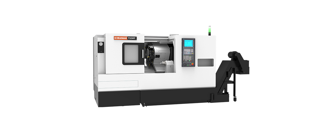
The Chinese model page describes a servo-indexed, hydraulically clamped live-tool turret with Y motion for turning, milling, boring, drilling and tapping. For an offset hole, flat or pocket, send its location from the turning datum and the complete holder approach. Request the usable Y range, C-axis operation, live-tool speed/power and simultaneous functions for the selected control.
Its reviewed Chinese table gives 300 mm maximum machining diameter, 371 mm maximum length, 195 / 500 mm X/Z travel and 12 tool positions. Main-spindle reference is 5000 rpm, A2-6 and 11 / 15 kW continuous / 30-minute. These figures describe the reviewed reference, not the English page’s different length/Z/W entries.
Check the tool at the awkward approach.
A radial drill, axial holder and milling cutter occupy different space around the chuck, turret and any support. Check reach at the most distant offset, clearance across jaws and the fully indexed turret, and the longest loaded holder. Specify tool coupling, mounting orientation and sister-tool needs rather than assuming 12 positions mean 12 usable powered tools.
The Chinese table does not state Y travel or bar capacity. Its 62 mm spindle-bore entry does not resolve either. The English T55MY table adds Y and W data while differing in machining length and Z travel; those entries are not combined with this Chinese build. Request a consistent axis diagram and build sheet. Do not give MY a sub-spindle merely because another regional table contains a W row. Open the T55MY reference ↗
Front and reverse-end machining
T55MS: the handover must preserve your datum.
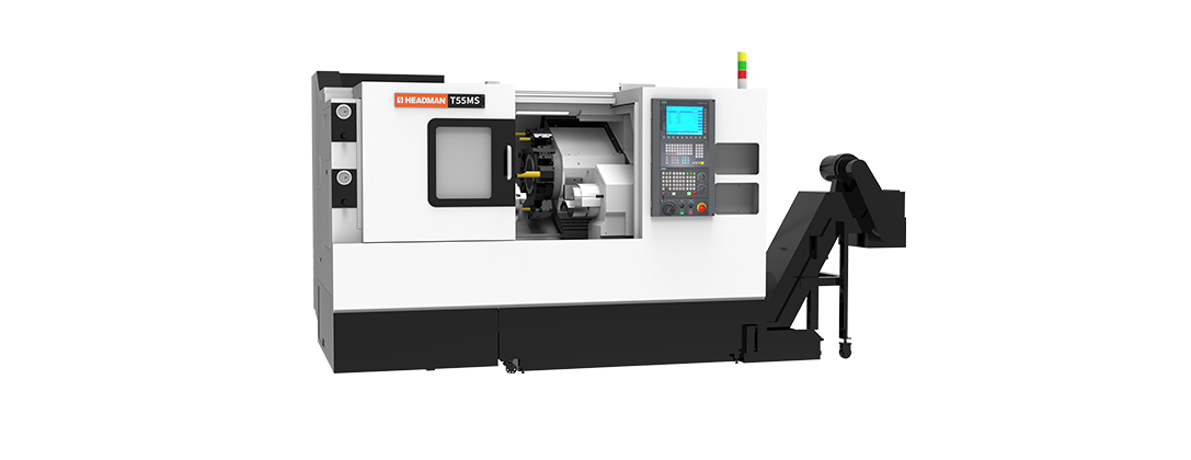
The manufacturer describes synchronized docking between two spindles to machine both ends with less manual intervention. Plan which surface the receiving chuck grips, how far the part transfers and which datum carries through. Review grip length, jaw contact, deformation, orientation and chip-free seating before treating handover as a finished-part process.
Put both chuck arrangements on the drawing.
The reviewed Chinese table lists 300 mm maximum machining diameter, 429 mm maximum machining length and 180 / 535 mm X/Z travel. Main-spindle reference is A2-6, 5000 rpm and 11 / 15 kW continuous / 30-minute, with 12 turret positions. It does not give the receiving spindle’s bore, speed/power, stroke or gripping load.
Ask for those secondary-spindle figures and the allowable synchronization/transfer conditions separately. Bar capacity is blank in this table. Neither a 62 mm main-spindle bore nor the MY version’s motion data is a substitute for the MS workholding specification.
Demonstrate the transfer and recovery sequence.
Include jaw opening, docking, gripping confirmation, parting-off if applicable, retraction and reverse-end access. Agree the control interlocks and recovery from a stop during handover. The reviewed MS page describes a powered turret, but does not establish Y motion; the old English MS address now leads to MSY, a different designation.
Time the accepted two-end part including loading, transfer, tool checks, chip clearing and inspection. A quoted turret indexing time is not the time of a complete process. Open the T55MS reference ↗
Prove the feature that depends on your setup.
Shaft: after the support is released
Use the proposed stock/material condition, jaws and tailstock settings. Measure roundness, straightness, diameter and datum relationship under the drawing’s agreed inspection conditions after release. Review tool wear and slender-part deflection rather than accepting an unloaded-axis number as the result.
MY: from turned datum to milled feature
Machine the critical offset hole/flat with the intended live holder, Y/C functions and programme. Inspect its location/orientation to the turned datum. Include clearance, chatter-sensitive projection, indexing and repeated seating in the trial.
MS: across the transfer
Measure front/reverse-end concentricity, runout or face relationship after handover and unclamping. Repeat the accepted sequence with production jaw contact, chip conditions and offset policy. Agree the sample and measurement method before shipment.
T55/500 publishes 0.008 mm X/Z bidirectional positioning and 0.003 mm repeatability; the reviewed MY/MS Chinese tables do not provide those figures. Axis tests are distinct from the part characteristics above. Obtain the selected serial machine’s test method, conditions and results, together with a released-part acceptance report. No machining tolerance, cycle time or hard-turning result is guaranteed from spindle ratings.
Connect manufacturing evidence to the delivered machine.
Headman’s company materials place its origin in 1993 and describe CNC lathe development, production and sales alongside flexible automation. Its manufacturing page identifies Yuhuan Puqing and Shamen facilities plus a Shanghai research centre. It describes precision-part machining, controlled-environment assembly and digital production tracking, with laser-interferometer, coordinate-measuring and balancing equipment in quality control. These are the manufacturer’s published facilities and methods, not an independent inspection of the machine you will receive.
The 28 August 2026 half-year issuer filing identifies 浙江海德曼智能装备股份有限公司 and SSE STAR stock code 688577, with its office in Yuhuan. The filing provides a dated entity cross-check; it is not a machine certificate, and its interim financial report is unaudited.
Request serial-unit spindle/axis inspection, turret positioning checks, thermal conditions and the actual cut report. Specify the control version, enabled turning/live-tool/transfer functions, CAM or conversational-programming scope, fixture and automation interfaces. For a bar feeder or robot, add guarding, interlocks, remnant/part handling and recovery, not just the loader’s name.
Identify the contracting entity, build location, destination installer and support provider. Obtain the whole installed floor plan: the published machine body does not include every feeder, conveyor, electrical cabinet or service clearance. Agree power, air/coolant, commissioning, training, warranty response and the spare spindle/turret/holder parts relevant to your selected build.
Keep the feature and handover requirements together.
Include material and blank/bar condition; turned datum and difficult feature; chuck/collet, jaws, support and grip length; front/reverse-end operations; offset coordinates and tools; selected model/revision, spindle and control; bar feeder/rotary or transfer needs; released-part inspection; repeated batch/changeover target; floor plan, utilities and destination. Ask for one coherent build and a trial on the operation that creates your next setup.
This page remains a technical reference while transaction arrangements for this record are reviewed separately. Browse manufacturer references ↗