

浙江恒大数控装备有限公司
Zhuji / Shaoxing, Zhejiang
Hengda: match the part to the turning configuration.
Compare HL18-T250, HL205-T500 and HL256-T500 using their own cutting envelopes, bar capacities and tool layouts. Y-axis and second-spindle builds are separate choices.
Company and three original series tables reviewed 8 October 2026
Start with the blank and the finished diameter
Short disc or short bar-fed part
HL18-T250 lists Ø300 mm maximum turning diameter and 250 mm maximum turning length with Ø36 mm bar capacity. Check the chuck/jaw contact and protruding tool before choosing it for a disc; its Ø400 mm bed swing is a separate clearance reference, not the cutting diameter.
Shaft with a supported end
HL205-T500 lists Ø382 mm maximum cutting diameter and 485 mm cutting length, while HL256-T500 lists Ø480 mm and 500 mm. Define the unsupported length, tailstock contact and tool approach from the actual shaft drawing. Tailstock, chuck and tool-holder space have to work together in the offered build.
Compare the complete T-column, not the largest family values
Scroll horizontally to compare all three configurations. On a keyboard, focus the table and use the arrow keys.
| Reference | HL18-T250 ↗ | HL205-T500 ↗ | HL256-T500 ↗ |
|---|---|---|---|
| Cutting diameter / length | Ø300 / 250 mm | Ø382 / 485 mm | Ø480 / 500 mm |
| Bed swing | Ø400 mm | Ø560 mm | Ø570 mm |
| Bar / spindle bore | Ø36 / Ø45 mm | Ø45 / Ø56 mm | Ø52 / Ø61 mm |
| Spindle / chuck | 4500 rpm / A2-5 / 6 inch | 4500 rpm / A2-5 / 6 inch | 4000 rpm / A2-6 / 8 inch |
| X / Z travel | 170 / 300 mm | 195 / 500 mm | 240 / 525 mm |
| Turret positions | 8 / 12 reference alternatives | 8 | 12 |
| Machine mass | 2300 kg | 3400 kg | 4800 kg |
The three columns give 30 / 30 m/min X/Z rapid movement. Rapid speed does not establish the cycle time through cutting, indexing, loading and inspection. Bar capacity is also separate from spindle-bore diameter; confirm the actual chuck tube, liner, feeder and supported bar length.
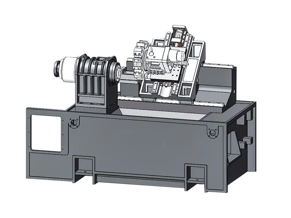
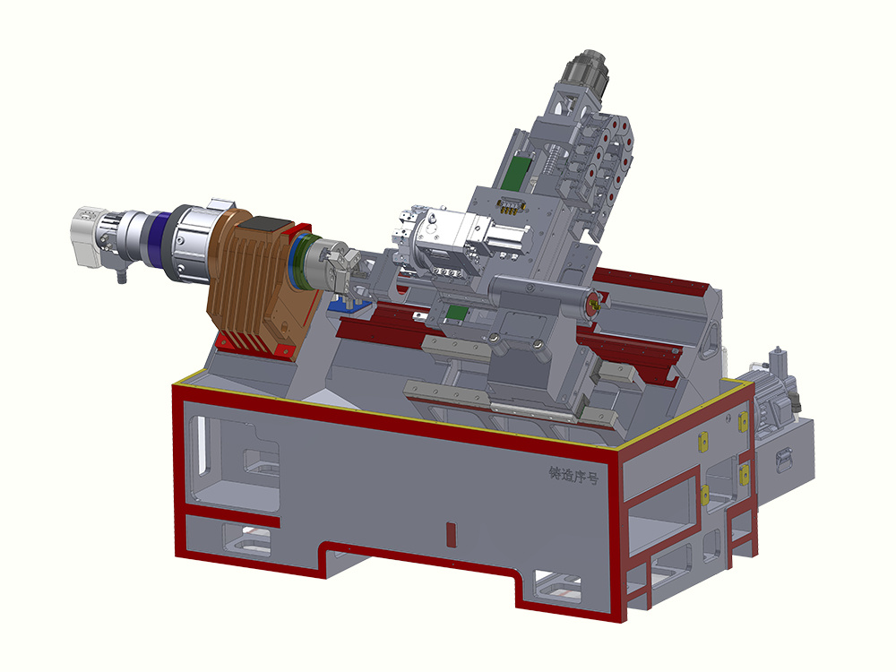
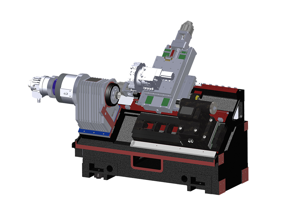
Resolve the chuck, tailstock and occupied turret as one envelope
At the chuck and the front shoulder
Send the jaw projection, gripping contact and largest shoulder, together with the actual turning and boring holders. HL205-T500 lists 25 × 25 mm turning shanks and Ø32 mm boring shanks; HL256-T500 lists 25 × 25 mm and Ø40 mm. A shank-size reference is not a guaranteed cutting depth or free space for the entire holder.
At the supported end
The HL205-T500 column lists a Morse 4 tailstock taper and an 85 mm tailstock-travel reference. HL256-T500 lists a Ø100 mm hydraulic sleeve with 125 mm sleeve stroke and Morse 5. These are different references; obtain the complete tailstock position/stroke drawing, alignment and support force for the shaft.
At the tool change
Model every occupied station with holder, cutter and boring-bar projection against jaws, workpiece and support. Identify turret indexing, interlocks and the safe path through approach, cutting, retract and change. The neighbouring Y or S configuration can change tool space and cutting envelope even when the family name stays the same.
A Y-axis or second spindle needs a different configuration
The 20-series table separately lists Y versions with ±35 mm Y travel. The 25-series table separately lists Y and S versions, including a sub-spindle on S entries. The reviewed T columns do not list those axes or a sub-spindle. Treat them as separate offers, with their own cutter reach, transfer/support and control details.
The site uses turning-milling category language across the family. That wording is not proof that these three T machines include a powered turret, continuous C-axis interpolation or simultaneous milling. If the part needs cross-holes, flats or an off-centre feature, specify live-tool speed/torque, holder interface, C-axis functions and any Y travel, then require a demonstrated cycle on the exact offered build.
The larger family description includes automation and spindle/chuck options. Confirm the supplied feeder, receiver, extraction/chip equipment, guarding and cycle interfaces. For the main spindle, obtain the complete continuous/intermittent torque-power curve; a catalogue maximum torque is not available at every spindle speed.
Use the shaft or disc that makes the choice difficult
Set the real locating arrangement
Use production material and blank allowance, the intended jaws/liner and tailstock support. Identify the critical shoulder, bore, unsupported length and datum. Fix clamp force, tool projection and inspection after release.
Prove the complete program
Run roughing, finishing, boring/threading and each tool change with the actual control and spindle duty. For optional bar feed or automation, include loading, remnant handling and safe recovery. Retain program, offsets, tool and configuration revisions.
Measure accepted output
Inspect drawing dimensions, concentricity/runout and surface after unclamping under agreed measurement conditions. Repeat the supported part and record tool condition, rejects and the elapsed loading-to-inspection cycle. Axis positioning figures are not a guarantee of every finished part.
Confirm the contracting company and delivered installation
The official company account describes the HD/Hengda machine-tool business and its Tonglu and Zhuji manufacturing/logistics sites. Its footer distinguishes 浙江恒大数控装备有限公司 at the Zhuji headquarters from 浙江恒大数控机床制造有限公司 at the Tonglu machining location. The signed quotation, invoice, warranty and delivery record should identify the responsible legal company and actual build.
A Zhuji 2024 proposed employment-stabilisation support list names 浙江恒大数控装备有限公司 at entry 2024. This supports a dated company-identity check; it is a proposed-support record, not a machine inspection or certification. Promotional history, output and certification wording is not used to promise delivered-part performance.
For HL205-T500, the catalogue distinguishes a right-discharge 3290 × 1540 × 1710 mm arrangement from a rear-discharge 2355 × 2355 × 1710 mm reference. Match the actual chip system and service access to the destination floor plan. HL256-T500 lists 3975 × 2140 × 1910 mm and 25 kVA total capacity; confirm auxiliaries, foundation, lifting, utilities, levelling, commissioning and training in the ordered schedule.
Request the exact parameter/tool/fixture drawings, acceptance part, spare/support responsibilities and program backups through CNCVerified.
Send the finished part, blank and tool layout
Include material, drawing/datums, disc or bar size, gripping and unsupported lengths, jaw/liner/tailstock setup, all tool holders and projections, live-tool/Y/sub-spindle requirements, accepted-output target, inspection method and destination chip-discharge/service space.
Send Hengda RFQ ↗