

科德数控股份有限公司
Dalian, Liaoning · five-axis machines, controls and components
Kede: fit the fixture through the five-axis motion.
Compare the DMC50 cradle with KHMC63 U and KHMC80 U horizontal machines. Start with the swept setup and the actual spindle package.
Check the geometry ↓Kede RFQ ↗
Original model pages and manufacturer sample; August 2026 issuer filing · reviewed 8 October 2026
Send the fixture assembly, not just a bounding box.
Kede designs five-axis equipment together with numerical controls, drives, feedback and machine components. That integration matters when the quotation covers a complete machining process. It does not remove the need to check tool reach, rotary motion, compensation and the part after unclamping.
Compact part with several inclined features
Start with the DMC50 cradle arrangement. Check the part plus base plate, clamps and holders through the required orientations. Its optional turning table has a different turning load from its milling load; a milling-only build cannot be priced as an integrated turning process.
Specify indexed 3+2 positioning or simultaneous five-axis cutting on the drawing. Ask for the machine-axis diagram, the tool/fixture collision review and the functions needed to run the supplied CAM programme. A five-axis designation is not a guarantee that your deepest feature is accessible in one setup.
DMC50: keep the tool-change allowance separate from machining travel.
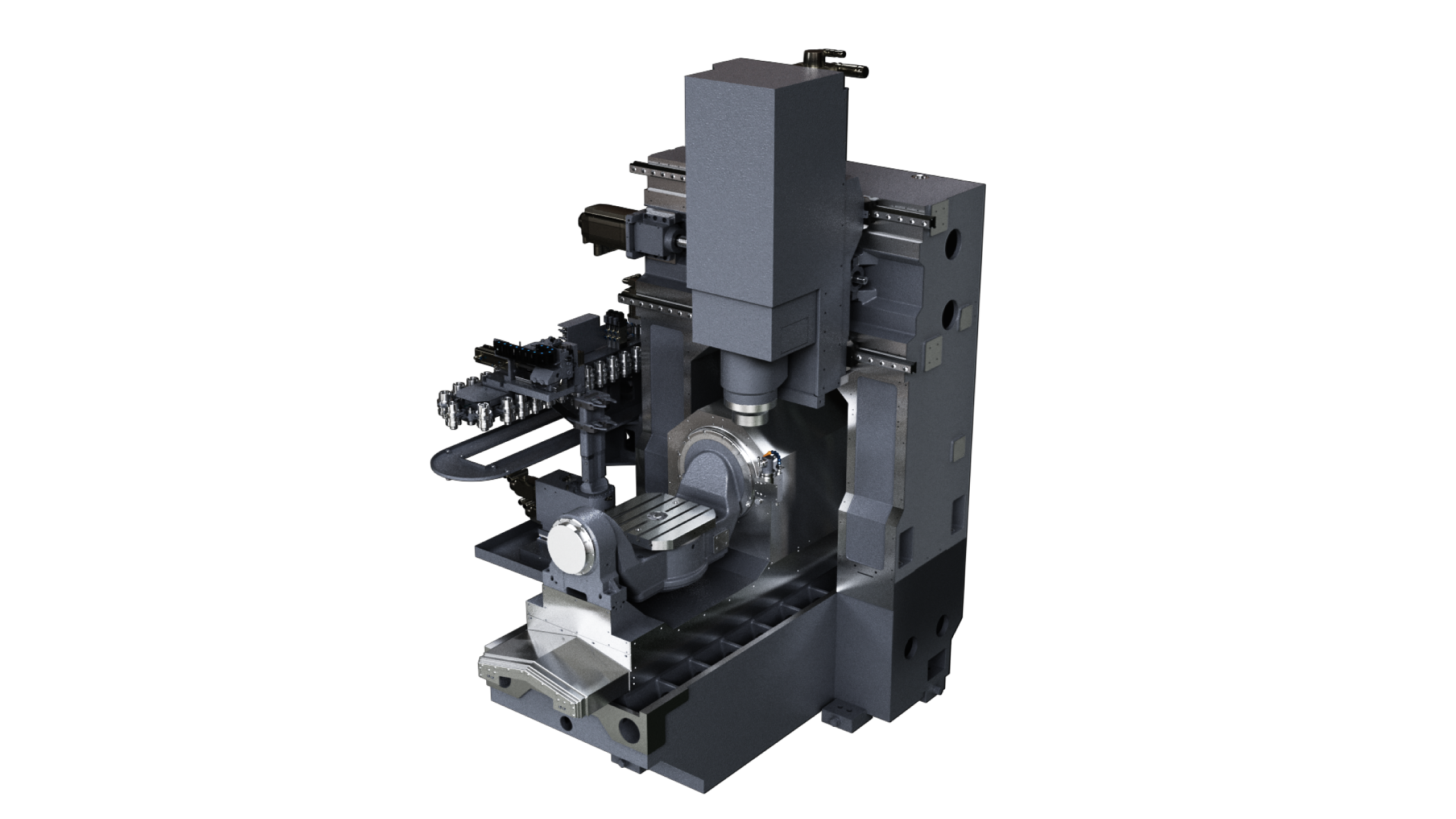
Travel and the rotating fixture
The exact model table writes X/Y/Z as 450 + 75 (tool change) / 600 + 25 (tool change) / 400 (375) mm. The extra X/Y allowance is not additional machining stroke; the bracketed Z value needs the selected build explained. Nose-to-table distance is 150–550 (150–525) mm. Resolve those bracketed limits on a signed working drawing.
Table 1 is Ø450 × □370 mm, rated 250 kg, with A/C maximum speeds 60/100 rpm. The separate Ø370 mm Table 2 entry lists 250 kg for milling, 150 kg for turning and 2000 rpm turning speed. Confirm which table, clamp arrangement, imbalance limits and module are included; do not apply 250 kg to a turning operation.
Tool package, not the highest headline speed
HFS15020/24 uses HSK-A63 and distinguishes 20000 rpm grease lubrication from 24000 rpm oil-air lubrication. The HFS17018-MT milling/turning spindle is a separate 18000 rpm HSK-A63 entry. Other packages reach 30000 rpm with HSK-A50 or 40000 rpm with HSK-E40; their ratings and holders are not interchangeable.
The standard magazine entry is 32 tools, with 70 mm adjacent-tool diameter versus 110 mm without adjacent tools, 250 mm length and 7 kg mass. Map occupied pockets and gauge lengths. The published 3-second tool-to-tool change is not the time between two accepted cuts. Open the full DMC50 configuration reference ↗
KHMC U: more room also changes the spindle and installation.
| Working reference | KHMC63 U | KHMC80 U |
|---|---|---|
| Maximum workpiece sweep diameter | 800 mm | 1000 mm |
| Listed square table, marked non-standard | 630 × 630 mm | 800 × 800 mm |
| Maximum workpiece mass | 1500 kg | 2000 kg |
| X / Y / Z travel | 1000 / 1000 / 1000 mm | 1200 / 1200 / 1200 mm |
| Current-table spindle reference | 18000 rpm; HSK-A63, A100 marked optional | 12000 rpm; HSK-A100, A63 marked optional; 8000 rpm alternative entry |
| Current-table magazine | 40; 60 marked optional | 60; 40 marked optional |
Swipe the comparison on a narrow screen. These are current published reference entries; request one coherent delivered build.
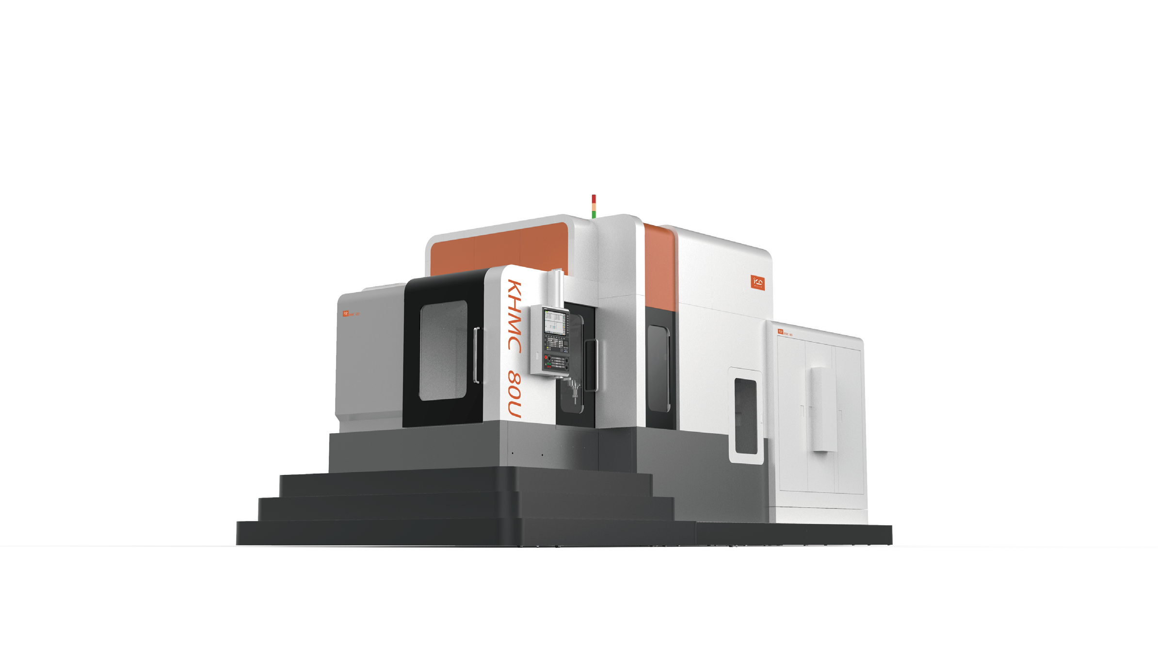
Review head access, table load and coolant as one setup.
The current table’s KHMC63 U head-centre/table range is 50–1050 mm and nose/table range 0–650 mm. KHMC80 U lists 80–1280 mm and 0–935 mm. These references do not establish clearance for every tilted head, long holder and raised fixture. Ask for full swept geometry, payload/centre-of-gravity conditions and the loading route.
The manufacturer describes rear-central chip discharge, direct-drive rotary components and a GNC62 bus control. Pallet exchange is described as an option for smaller members of the family. Confirm the actual pallet system and its separate payload, tool capacity and chip/coolant package. U is not UT: the separately named UT family adds turning capability; a rotary axis on U does not establish a quoted turning process.
The original sample and site contain revisions to spindle, magazine and other table entries. The current site also uses inconsistent B/C naming around rotary motion. No old and new maxima are combined here; obtain the axis drawing, spindle-code data and revision-controlled table. Paired tool size/length/mass entries need their configuration conditions explained before loading the magazine.
Make the control-to-CAM handover part of acceptance.
Define the machine configuration
Fix spindle/table/module codes, tool and fixture coordinates, rotary conventions, travel restrictions and control software/options. For turning, include table balance and clamp limits, spindle orientation/locking and the actual turning-holder arrangement.
Prove the supplied programme
Kede’s GNC62 sample describes tool-centre-point control, inclined machining, probing/tool-setting integration and compensation functions. Verify the functions licensed on the offered machine, the CAM postprocessor and the simulation’s machine model. Check safe retracts, singular or limiting orientations and restart from an interrupted toolpath with the real holders.
Agree support deliverables
Include backed-up parameters/PLC and compensation records, approved postprocessor files, operating/programming training and a controlled recovery procedure. Establish who updates these after a service intervention and who can diagnose the control and mechanical process at the destination.
Test the tilted feature after the part is released.
Choose a part that exposes the longest holder, largest fixture sweep or critical relationship between inclined features. Use the quoted material, fixture, table load and programme. Agree warm-up, compensation, probing policy, repeated setups and measurement conditions before timing the accepted part.
- DMC50 milling: inspect feature position/orientation and surface after the cradle has moved through the required attitudes. Include unclamping and reseating, not only an unloaded linear-axis test.
- DMC50 with turning: inspect the turned/milled datum relationship after release at the turning payload and balance conditions agreed for Table 2.
- KHMC U: verify deep-feature reach and multi-face datum relationships with the selected head/spindle and fully loaded fixture; demonstrate chip removal and safe access/restart.
The DMC50 table gives 5/4 μm linear positioning/repeat positioning and 5/4 arcseconds for A/C; KHMC63/80 U publish 0.008/0.005 mm linear references. These are machine test entries, not the tolerance of your finished feature. Request serial-machine geometry, rotary/volumetric checks and the trial’s actual measurement record.
A machine-and-control builder; a specific support contract.
The August 2026 interim filing identifies 科德数控股份有限公司 / KEDE NUMERICAL CONTROL CO., LTD., code 688305, in Dalian. Its company material describes machines, GNC62 controls, drives, motors, rotary heads/tables, spindles and feedback/probing components. That published scope explains the integrated offering; it is not independent proof of the accuracy or availability of an individual serial unit.
Request the contracting entity, destination-specific safety/installation documentation, delivered software/functions, full utilities and maintenance clearances, commissioning plan and spare-component support. Agree the language and scope of training and how a failed spindle, encoder or controller is diagnosed and replaced. A group or company capability statement does not define local response time.
Tool grinding, bridge gantries, blade/other specialist machines and the wider DMC/KHMC catalogue are separate projects. Their capabilities are not transferred to these three model references.
Send the tilted setup and the feature that must stay on datum.
Provide the part/fixture/holder assembly, material and blank condition, feature datums/tolerances, maximum load and centre of gravity, required orientations and CAM system. Say whether turning is required, give the intended tools and production mix, and identify the installation country and utilities.
Ask for one signed build sheet, swept clearance review, accepted sample programme/measurement method, itemised control/modules and destination commissioning/support scope through CNCVerified.
Prepare a Kede RFQ ↗