

巨鑫机床有限公司
Wenling, Taizhou, Zhejiang
Juxin twin-station turning: match the part and its second setup
Separate disc jobs from shaft jobs. Then define how two independent vertical turning stations hold, turn over and inspect the same part through its two operations.
Three official model tables, manufacturing introduction and national standard record reviewed 8 October 2026
Start with the shape that actually needs turning
Juxin's catalogue separates disc-oriented twin vertical lathes from shaft-oriented models. JXLC40D and JXLC63D offer different disc diameters and heights; JXLCS45A lists separate shaft and disc capacities. Their swing diameters describe clearance, not the largest diameter that can be cut with the proposed jaws and tools.
| Part check | JXLC40D · discs | JXLC63D · larger discs | JXLCS45A · shafts / discs |
|---|---|---|---|
| Listed turning diameter | 400 mm | 530 mm | Shafts 180 mm; discs 210 mm |
| Listed part height / length | Height 300 mm | Height 400 mm | Length 600 mm |
| Swing diameter | 450 mm | 630 mm | 450 mm |
| Inner-bore machining entry | Within 300 mm | Within 300 mm | Not separately defined in this table |
| Published spindle-speed entry | 3000 rpm | 1000 rpm | 2500 rpm |
| Hydraulic-chuck choices | 8 / 10 inch | 15 / 18 inch | 8 / 10 / 15 inch |
| Spindle interface entries | A2-6 | A2-8 / A2-11 | A2-6 / A2-8 |
| X / Z travel | 250 / 610 mm | 250 / 610 mm | 250 / 610 mm |
| Existing model details | JXLC40D ↗ | JXLC63D ↗ | JXLCS45A ↗ |
Swipe to compare the disc and shaft limits separately.
JXLCS45A's 450 mm swing does not make it a 450 mm disc-cutting machine: the reviewed table lists 210 mm for discs. The catalogue's HA and CX variants have different lengths or turning/milling features. Keep them separate from an A quotation rather than adding their figures to this reference.
Write an operation sheet for each station
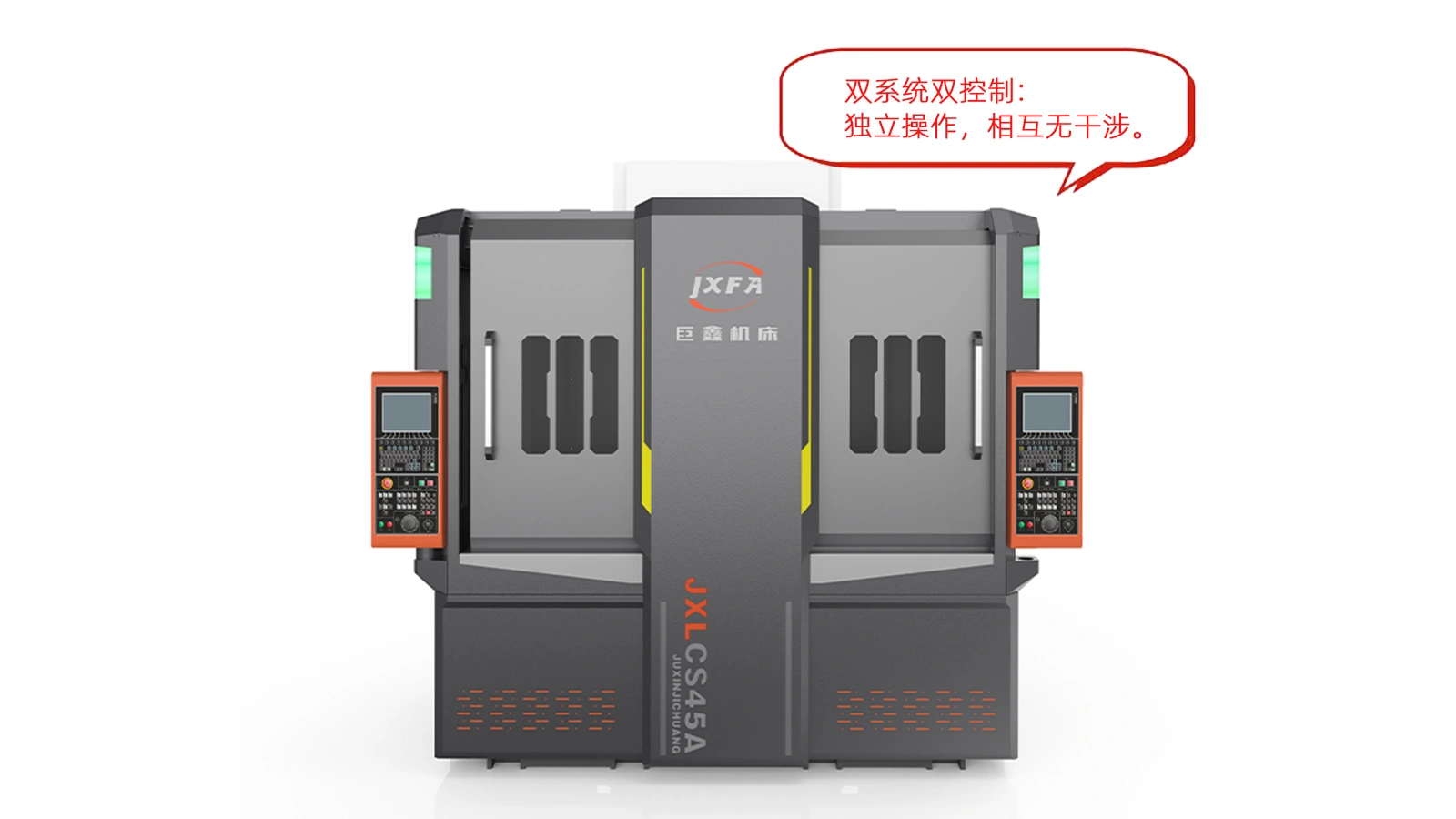
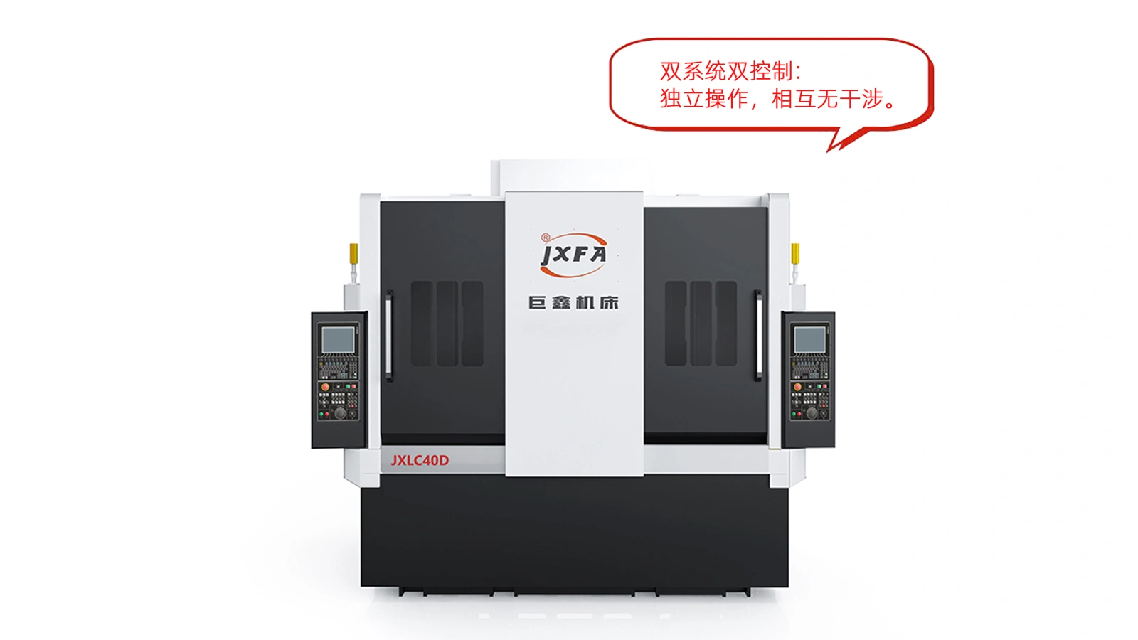
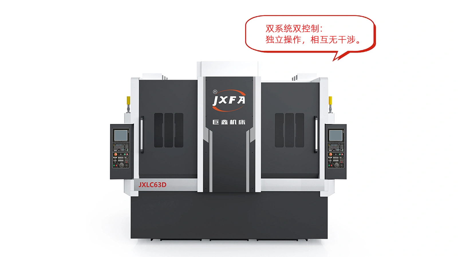
The manufacturer describes two spindles, two work stations and independent control systems. That arrangement can support different operations on opposite sides, but it does not by itself establish an automatic transfer spindle or a finished part in one uninterrupted clamping.
Create the first reference
Identify the raw locating surface, grip diameter, jaw contact and support. Mark the faces, bore or shaft features finished in this operation. Retain the datum needed to locate the second setup; do not use an unfinished casting surface as an assumed precision reference.
Define the handoff
Show how the part is released, oriented and presented to the second station. Specify manual, robot or other handling, grip points and any intermediate inspection or cleaning. Confirm whether the first finished reference is protected from jaw marks and chips.
Finish relative to that datum
Show the second fixture's locating contacts and clamp force. For discs, agree face runout, concentricity and thickness references; for shafts, agree support, runout and shoulder relationships. The accepted condition is the released part after both operations.
Make the quotation describe both cutting units
- Chuck, jaws and support
- Choose one chuck/interface combination and provide jaw height, grip length and the tool-access drawing. A2-6, A2-8 and A2-11 are spindle-interface designations. They appear under a mislabeled bore heading on the source pages and must not be treated as through-bore dimensions in millimeters.
- Turret and tool clearance
- The tables list eight- or twelve-position and powered-tool alternatives, with 25/32 mm tool-body entries. Specify the installed turret, holder and powered-tool functions. The X-travel entry also carries a disc center-crossing limitation; obtain its exact definition and demonstrate face/bore toolpaths with the real turret and jaws.
- Motor and control version
- Motor entries are 7.5/11 kW for 40D, 18.5/22 kW for 63D and 11/15 kW for 45A. Their duty/version relationship is not defined by the slash. Select the supplied motor, torque curve and controller. Huazhong, KND, GSK and Siemens are named choices, not four controls delivered together.
- Positioning versus output
- The reviewed pages give 10 m/min rapid movement, 0.001 mm minimum input and 1.5-second turret-change entries. Input increment is not finished-part accuracy; tool change is not the complete cutting or handling cycle. Compare measured output from the two agreed operations.
Let the slower operation determine the robot queue
The disc-model pages illustrate four- and six-machine lines; the shaft page illustrates three- and five-machine arrangements. Their described cycle thresholds are planning examples. A robot layout must be sized for the actual mix of OP10, OP20, tool changes, inspection and loading tasks.
- Balance the two operations. Record cutting and handling separately, including time to turn, clean and re-grip. Establish whether stations work on identical parts or successive operations, and how unfinished parts are tracked.
- Plan buffers and recovery. Define storage positions, orientation checks, rejected-part routing and restart after a stop. Demonstrate the robot's response when a machine is changing tools or temporarily unavailable.
- Check the occupied cell. Use the actual delivered outline, guarding, chip bins, material storage and operator/maintenance access. Catalogue machine dimensions and advertised floor-space savings do not establish the installed line footprint.
- Validate safe access. Agree interlocks, guarding and safe manual setup/service procedures for the supplied cell. A manufacturer's non-interference statement is not a substitute for the delivered risk assessment and commissioning test.
Connect the machine inspection to your finished part
Juxin's company introduction describes precision assembly, scraping of mating surfaces, Wenzel coordinate measurement and Renishaw laser-interferometer checks. These are manufacturer descriptions of its production and inspection methods. Request the actual machine's acceptance records and the part trial; naming an instrument does not supply a measurement result.
The national standards platform record for JB/T 15206.1-2025 names 巨鑫机床有限公司 among the drafting organizations. It was published 17 December 2025 and implemented 1 July 2026. Drafting participation is not certification of these vertical lathe models; agree the applicable test scope separately.
- Run both setups on the actual blank. Retain material, hardness, drawing revision, fixture/jaws, cutters, offsets and program. Include the part with the most difficult grip or cross-setup datum.
- Inspect after OP20 and release. Measure dimensions and the specified face/bore or shaft relationships using agreed datums and instruments. Include clamp-sensitive features and the required surface condition.
- Repeat the complete route. Test loading, turning, inspection, buffers and stop/restart with the intended part mix. Record the accepted output and rejects, rather than repeating an advertised percentage gain.
The official introduction identifies Juxin Machine Tool Co., Ltd. in Wenling and describes dedicated shaft/disc machines, facing-and-centering equipment and automation. Its wider catalogue also includes mid-drive turning, grinding and other specialized routes. This page substantively reviews the three existing references above; broader families require their own process and configuration evidence.
Send the drawing and a two-operation sketch
Include blank/final dimensions, material/hardness/mass, OP10 and OP20 features, grip surfaces, critical cross-setup datums, fixture needs and inspection limits. Add part mix and batch, desired control/turret, manual or robot handling, full-cycle target, destination and the proposed disc or shaft model.
Send Juxin RFQ ↗