

湖南中大创远数控装备股份有限公司 · Changsha · Gear-making equipment
ZDCY: take the gear pair from tooth design to corrected contact
YKA2235 cuts bevel teeth. YK2035G and YKA2060 grind them. Define the tooth system and heat-treatment stage before comparing diameter or axis count.
Choose the cutting or grinding stage ↓Prepare a gear-machining RFQ ↗
Original model, software and company materials plus primary identity records reviewed 8 October 2026
Three machines, two different jobs on the tooth
ZDCY develops bevel-gear cutting and grinding equipment, cylindrical-gear machinery, measurement equipment and gear-process software. The existing three model records here address bevel-gear work. Bring the mating pinion and gear data, tooth system, handedness, mounting geometry, material and heat-treatment route; the same outside diameter can require different cutting methods, fixtures and finishing stages.
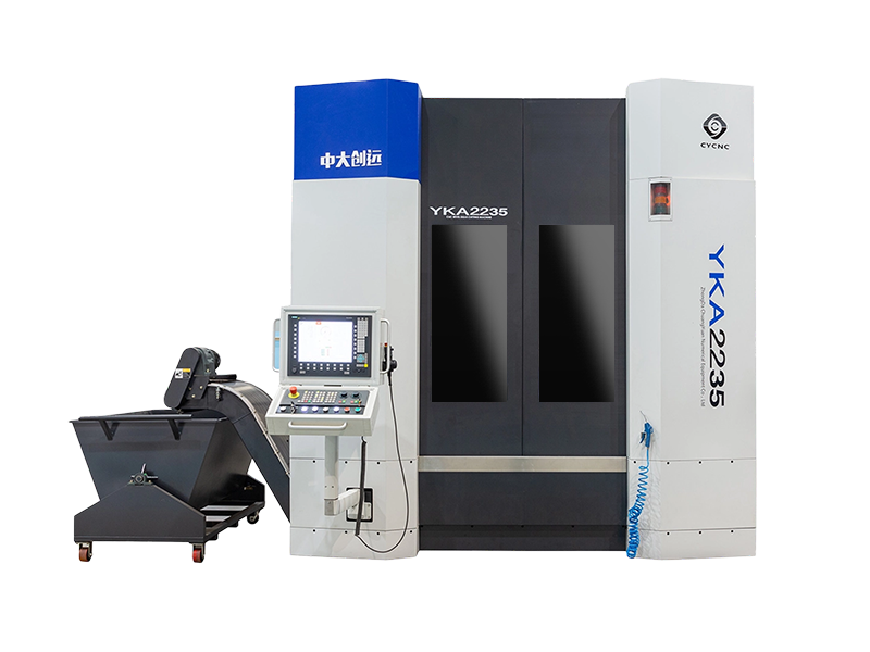
Cut the tooth geometry · YKA2235
The manufacturer describes six controlled axes with six-axis simultaneous motion, dry/wet cutting and inline chamfering. Its listed tooth-system routes include cycloidal constant-depth, circular-arc tapered-depth, face-gear, HRH and straight-bevel work. Select the precise process and cutter system with the gear drawing. This is a tooth-cutting machine, rather than a grinding step.
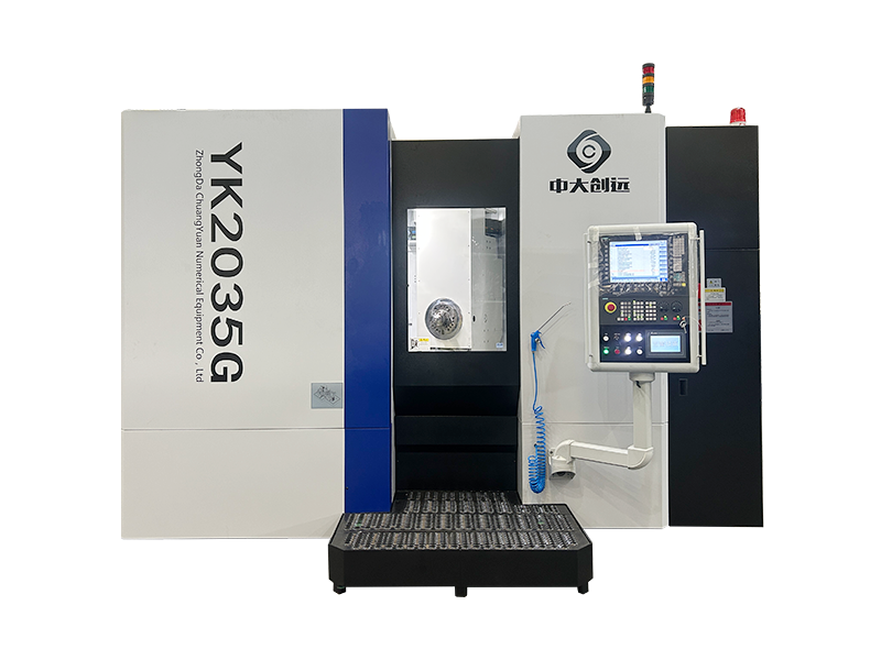
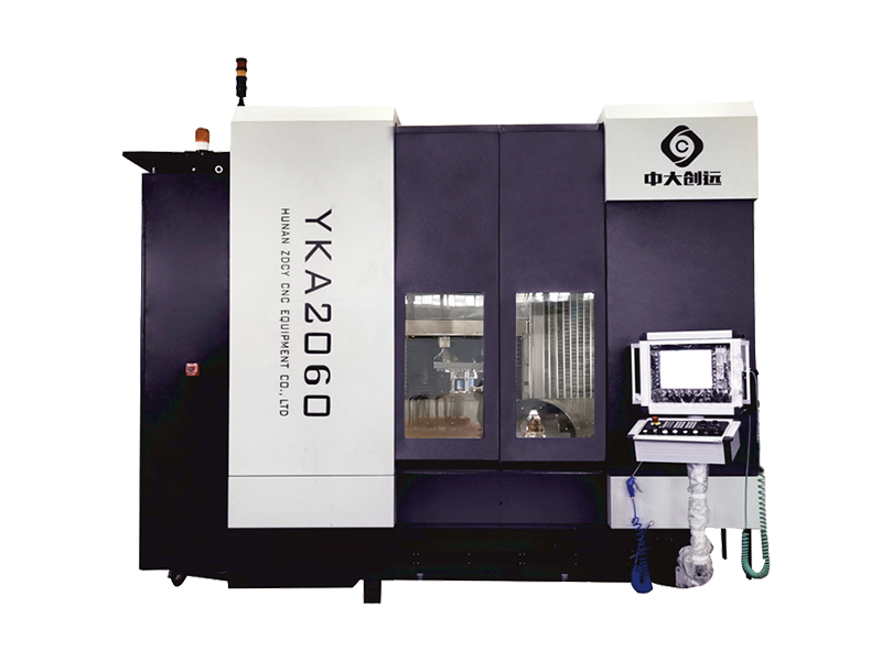
Grind the specified tooth flank · YK2035G / YKA2060
YK2035G offers seven-axis generating or eight-axis form-grinding arrangements, with five-axis simultaneous motion. YKA2060 is described as eight controlled axes and five-axis simultaneous motion, using generating or form grinding. Agree the tooth form, available allowance and wheel/dressing strategy; the machine's total axis count is not its simultaneous axis count.
Match the gear definition and the actual cutter or wheel
Swipe the table on a phone. Maximum diameter here is the gear-processing reference, not a general workpiece swing diameter.
| Separate source tables | YKA2235 · cutting | YK2035G · grinding | YKA2060 · grinding |
|---|---|---|---|
| Maximum diameter | 350 mm | 350 mm | 600 mm |
| Maximum face module | 10 mm | 10 mm | 15 mm |
| Teeth / maximum ratio | 1–200 / 200:1 | 1–200 / 200:1 | 1–200 / 200:1 |
| Tool reference | Face-milling cutter Ø3.25–9 in; face-hobbing cutter R39–105 mm | Grinding wheel Ø2.7–9 in | Grinding wheel Ø7.5–18 in |
| Machine net mass | 20,500 kg | 17,000 kg | 29,700 kg |
| Total machine power | 65 kW | 85 kW | 120 kW |
| Machine L × W × H | 3060 × 3240 × 3360 mm | 4100 × 2800 × 2900 mm | 4200 × 3500 × 3500 mm |
| Whole-machine occupied area reference | 5400 × 5200 mm | 5900 × 7500 mm | 7200 × 5200 mm |
The source specifies face module; do not substitute normal module without the gear definition. Cutter radius, cutter diameter and grinding-wheel diameter also use different conventions. Check tooth depth, face width, bore/fixture interface and cutter/wheel clearance on the selected-machine drawing. Total machine power is not cutting-spindle power.
Close the loop on measured tooth error and mating contact
The manufacturer's CHIMES software description links blank design, machine/tool parameter calculation, contact analysis, tooth-error compensation and cutting/fixture simulation. It separately describes heat-treatment pre-compensation for cut teeth and tooth-surface compensation for grinding. Define which software modules, measurement equipment and data exchange are in the offer; a machine-control licence is not automatically a complete design-and-inspection system.
Freeze the tooth and blank definition
Provide both members of the pair, installation geometry, ratio, tooth system, face/normal module conventions and required flank modification. Agree the cutter/wheel and fixture before producing adjustment data.
Measure the actual stage
For cutting before heat treatment, define allowance and the later distortion/finishing route. For grinding, supply the heat-treated stock condition, hardness, distortion and available flank allowance. Agree dressing, cooling/filtration and thermal conditions with that stock.
Apply a traceable correction
Agree measurement datums, flank sampling, error-map format, correction limits and revision tracking. Re-measure the corrected gear and check the pair at the agreed mounting position; a software simulation is not the physical acceptance test.
The cutting page names HCS control software and the grinding pages HGS, integrated with Siemens ONE. Keep machine-operation software separate from CHIMES design/analysis modules and any optional loading or metrology package.
Leave room for the process equipment and the inspection route
The original tables list machine dimensions and larger whole-machine occupied-area references separately. Lay out the actual loader or manual access, cutter/wheel servicing, dressing, oil cooling/filtration, chip or dust handling and measurement path. Confirm which auxiliaries are included in the stated area and leave the access shown by the current installation drawing.
YKA2235 offers dry/wet routes, dust collection and an optional automatic door. YK2035G and YKA2060 describe independent grinding-oil cooling/filtration and oil-mist separation. Agree the plant utility loads, fire/oil handling responsibilities, lifting and floor/foundation requirements for the delivered package. An automatic door alone does not establish an automatic production line.
Accept the gear pair under its agreed operating conditions
Supply a representative pair and material/heat-treatment specification. Define the quality standard and edition, flank measurement, pitch/runout checks, roughness location and any surface-integrity requirement. The manufacturer's DIN-grade and roughness claims describe its published performance references; they do not establish the outcome for an unspecified gear, material or process.
For contact-pattern, transmission-error or noise requirements, agree mounting distance, backlash, test speed/load and the actual measuring or rolling-test equipment. Count loading, dressing, measurement, compensation and rejected parts in the complete cycle. A successful single flank scan does not by itself prove production consistency or loaded pair performance.
Connect the current company name with the dated records
The company identifies its Changsha operation as 湖南中大创远数控装备股份有限公司. Its published September 2026 licence bears the same unified credit identifier as entry395 in a 2023 government-hosted R&D funding proposal list, page8, which uses the earlier 有限公司 name. The licence and historical list serve different purposes; the list does not establish a current machine certification.
The national standards platform's JB/T15436.2-2026 record names the earlier company among the drafters of the CNC straight-bevel gear cutting technical specification. Its implementation date is 2 November 2026, after this review. Drafting involvement is not proof that a particular YKA2235 build has been certified to that standard.
The manufacturer describes process assistance, operator/application training and work instructions. Agree the contracting and manufacturing entity, delivered software licences, commissioning, trial acceptance, training language and destination service responsibilities in the purchase documents.
Send both gears and the process stage
Include pair drawings, tooth system/handedness, ratio, face/normal module, outside diameter and face width, blank/fixture data, material and heat treatment, cutting or grinding allowance, flank modification, measurement/loaded-contact criteria, batch/cycle target and destination. Identify software, tool/dresser, filtration, loading and measurement packages separately.
ZDCY RFQ ↗