

KAIDA · Zhuji, Zhejiang · Milling and turning equipment
KAIDA: choose the setup before the machine.
Compare KDVM1160L and KDVM1270L for a loaded milling fixture, or KDCL-28 for turning. The 28H and 28Y variants change cutting space and tooling; keep their figures separate.
Original company, model tables and standard record reviewed 8 October 2026
Does the blank locate on a fixture or rotate in a chuck?
KAIDA's catalogue covers vertical, horizontal and gantry machining centres, five-axis equipment, CNC turning, conventional lathes and other drilling/boring routes. Its company page identifies NATIONAL VICTOR for its domestic market and miUmac for overseas markets, explaining the miUmac marking on the original equipment photographs.
Plate, housing or milling fixture
Start with the KDVM vertical references when features are reached from above using a located fixture. The useful comparison is loaded table mass, furthest feature, spindle-nose clearance and holder approach—not the outside size of the blank alone.
Compare two KDVM setups ↓Rotating shaft or disc
Start with KDCL-28 and its variant table when the primary datum comes from turning. Check chuck grip, unsupported projection, tailstock/tool approach and secondary features before selecting base 28, 28H or Y-axis 28Y equipment.
Separate the turning variants ↓Extra travel also changes the loaded fixture and installation
Swipe the comparison sideways on a phone to read each complete column.
| Setup check | KDVM1160L | KDVM1270L |
|---|---|---|
| X / Y / Z travel | 1100 / 600 / 600 mm | 1200 / 700 / 700 mm |
| Table / rated load | 1200 × 600 mm / 800 kg | 1360 × 700 mm / 1000 kg |
| Nose to table | 120–720 mm | 190–890 mm |
| Spindle centre to column guide | 650 mm | 770 mm |
| T-slot layout | 5 × 18 mm wide, 100 mm spacing | 5 × 18 mm wide, 120 mm spacing |
| Spindle / motor | 8000 rpm / 11/15 kW pair | 8000 rpm / 11/15 kW pair |
| Rapid X / Y / Z | 36 / 36 / 30 m/min | 36 / 36 / 30 m/min |
| Outer size, excluding chip conveyor | 3200 × 2300 × 2700 mm | 3360 × 3450 × 2950 mm |
| Machine mass | 6.5 tonnes | 8.8 tonnes |
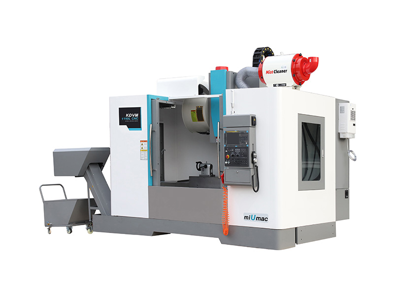
Check both ends of the nose window
1270L adds travel and a higher maximum nose position, but its published minimum is also higher: 190 mm rather than 120 mm. Check a shallow fixture with a short tool as well as a tall block with a long holder. More Z travel does not mean an unchanged near-table position.
Include the plate, vises, stops and all blanks in the 800 or 1000 kg setup. The table area is not axis travel. Confirm clamp interference, retract and tool-change positions. Both pages list BT40/Ø150 and an 11/15 kW motor pair; obtain the spindle drawing and duty/torque curves before interpreting the diameter or power notation.
Keep KDCL-28, 28H and 28Y cutting envelopes separate
The shared original table gives the same Ø520 mm bed swing and 8-inch hydraulic chuck reference for these variants, but different disc diameters, shaft lengths and travels. Bed swing describes clearance; it is not a promise to cut a Ø520 mm disc.
Swipe across base, H and Y columns. Only the existing base KDCL-28 product link is used below.
| Turning check | KDCL-28 | KDCL-28H | KDCL-28Y |
|---|---|---|---|
| Disc cutting diameter | Ø420 mm | Ø370 mm | Ø360 mm |
| Shaft cutting diameter / length | Ø250 / 500 mm | Ø250 / 420 mm | Ø280 / 420 mm |
| X / Z travel | 235 / 600 mm | 235 / 540 mm | 255 / 550 mm |
| Y travel | Not listed | Not listed | ±38 mm |
| Tailstock quill taper | MT4 | MT4 | MT5 |
| Tool stations | 12 | 12 | 12 |
| Motor pair | 11/15 kW | 15/18.5 kW | 15/18.5 kW |
| Net mass | 4300 kg | 4300 kg | 4800 kg |
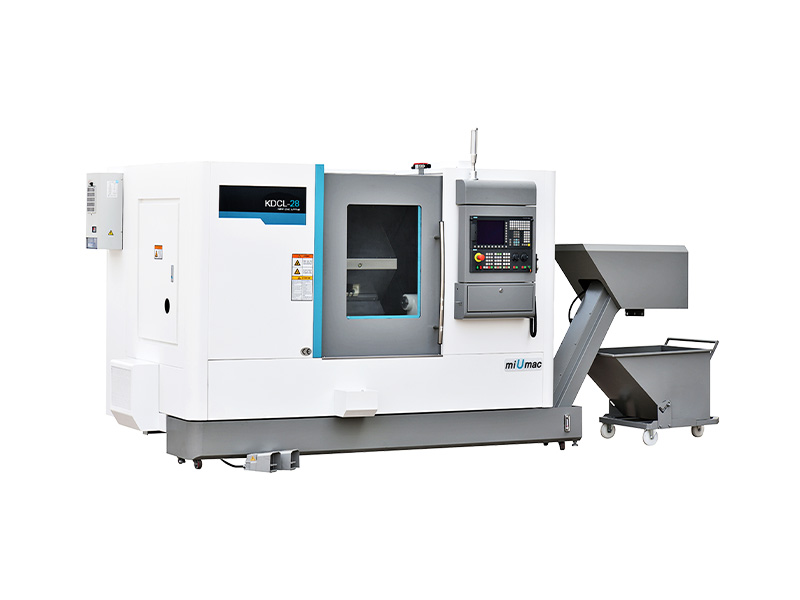
Long shaft, through-stock or off-centre feature?
The base 28 lists 600 mm Z travel but 500 mm maximum shaft cutting length. Check jaw projection, stock support, tailstock position and tool access for the actual part. Its bore/speed row publishes a Ø63/Ø65 and 4000/5000 rpm pairing with a parenthesised configuration note; obtain the selected spindle and complete stock-passage drawing, including liner, chuck and feed equipment.
For a secondary hole, flat or off-centre feature, ask which driven tools, C-axis functions and holders are fitted, and whether Y travel is required. Twelve stations alone do not establish powered-tool capability. The base OD holder reference is 25 × 25 mm with Ø40 mm internal tool; H uses 20 × 20 and Ø32 mm. Verify every holder's envelope instead of carrying base 28 tooling into H or Y.
KDCL-28 details ↗Use the loaded tool map and a released trial part
Milling: occupied tools and datum checks
The KDVM table lists 24 tools, Ø78 mm with adjacent positions occupied or Ø120 mm with those positions clear, maximum tool length 300 mm and mass 8 kg. Map the actual holders, cutters, probes and spare positions. Its 2-second tool-to-tool reference is not the complete machining cycle. Include fixture location, tool changes, probing, chip handling and released-part inspection in the trial.
Turning: grip, support and secondary operations
Define jaw contact and grip length, projection, cutting forces, support and the sequence of turning and any powered-tool work. Check runout and critical features after release as required by the drawing. The source's 0.001 mm minimum input unit is command resolution, not achievable part tolerance; the ≤0.006 mm repeat-positioning reference is likewise not a blanket finished-part guarantee.
For either route, send material and heat treatment, blank allowance, datum scheme and inspection method. Agree the control/build, tools and coolant settings used in the test. Compare the complete cycle and drawing-based result, with thermal and clamping conditions recorded.
Confirm the build package and the acceptance reference
KAIDA's Chinese company page traces its predecessor to Zhuji Machine Tool Works in 1952 and describes a 1997 restructuring. It describes Chengxi and Shuangqiao factories with forging, metal cutting, heat treatment, sheet-metal work, assembly and painting. Those are the company's published manufacturing scope; select the supplying entity, actual assembly site, build revision and destination service responsibilities in the quotation.
The national standards platform record for JB/T 10889.1-2026 lists 浙江凯达机床股份有限公司 as a drafting participant. Published 1 June 2026, it is scheduled to take effect on 1 December 2026. Drafting participation does not certify the machines above. Agree the applicable standard edition and actual acceptance tests in the contract.
The KDVM table names FANUC 0i MF (5); confirm the control version, language, interfaces, options and program compatibility for the delivered build. Its outer dimensions exclude the chip conveyor. Add conveyor, service access and opening clearances to the installation plan, and obtain lifting/foundation and utility drawings. On-site installation and factory training are described by the service page; agree scope, travel, costs and local responsibilities rather than assuming every destination is included.
Send the fixture or chuck setup with the drawing
Provide material/heat treatment, datums and tolerances, blank/fixture mass and envelope, clamps or chuck jaws, unsupported projection, tool/holder map, secondary milling needs, coolant/chip package, control, complete output target, inspection plan and destination. Identify 1160L, 1270L, base 28, H or Y, then request the selected build and trial conditions.
KAIDA RFQ ↗