
Wire EDM, small-hole EDM or die-sinking: start with the feature
Follow the electrode route, then check thickness, taper, depth and control options. Three exact Baoma records show what a headline specification leaves out.
Three drawings can all say “EDM” and still need different equipment: a profile that passes through the blank, a small hole, or a shaped pocket with a floor. Start with the feature and the electrode path. A large travel number or a high removal-rate headline cannot settle which process can reach the feature.
This guide uses three separately reviewed Baoma records to show how to read that distinction. They are examples of different processes, not a controlled productivity comparison. The Baoma factory profile explains the corresponding families and retained machine references. Manufacturer tables were re-read on 9 October 2026; the trial and handover steps below are CNCVerified's engineering checklist, not tested production results.
1. Draw the route into the feature
A contour through the blank
A wire needs a continuous route through the conductive workpiece. For an enclosed through-profile, identify the threading or starter-hole route and how the remaining slug is supported. Draw the top and bottom profiles if they differ. A wire contour is not the same task as sinking a closed-bottom pocket.
A small hole
Draw the entrance, bore direction, required depth and exit or blind-end condition. The electrode must approach the entrance with its guide and flushing arrangement, and must be withdrawn or replaced. A hole made to start a later wire operation is one stage in a process; it does not finish the wire contour.
A shaped cavity
A cavity also needs an electrode plan: material, shape, corner requirements, roughing and finishing allowances, and how replacement electrodes are located. Record whether X/Y setting, orbiting and electrode changes are manual or controlled on the actual machine. The controller designation alone does not explain the whole operation.
2. Read the wire model's taper condition separately from thickness
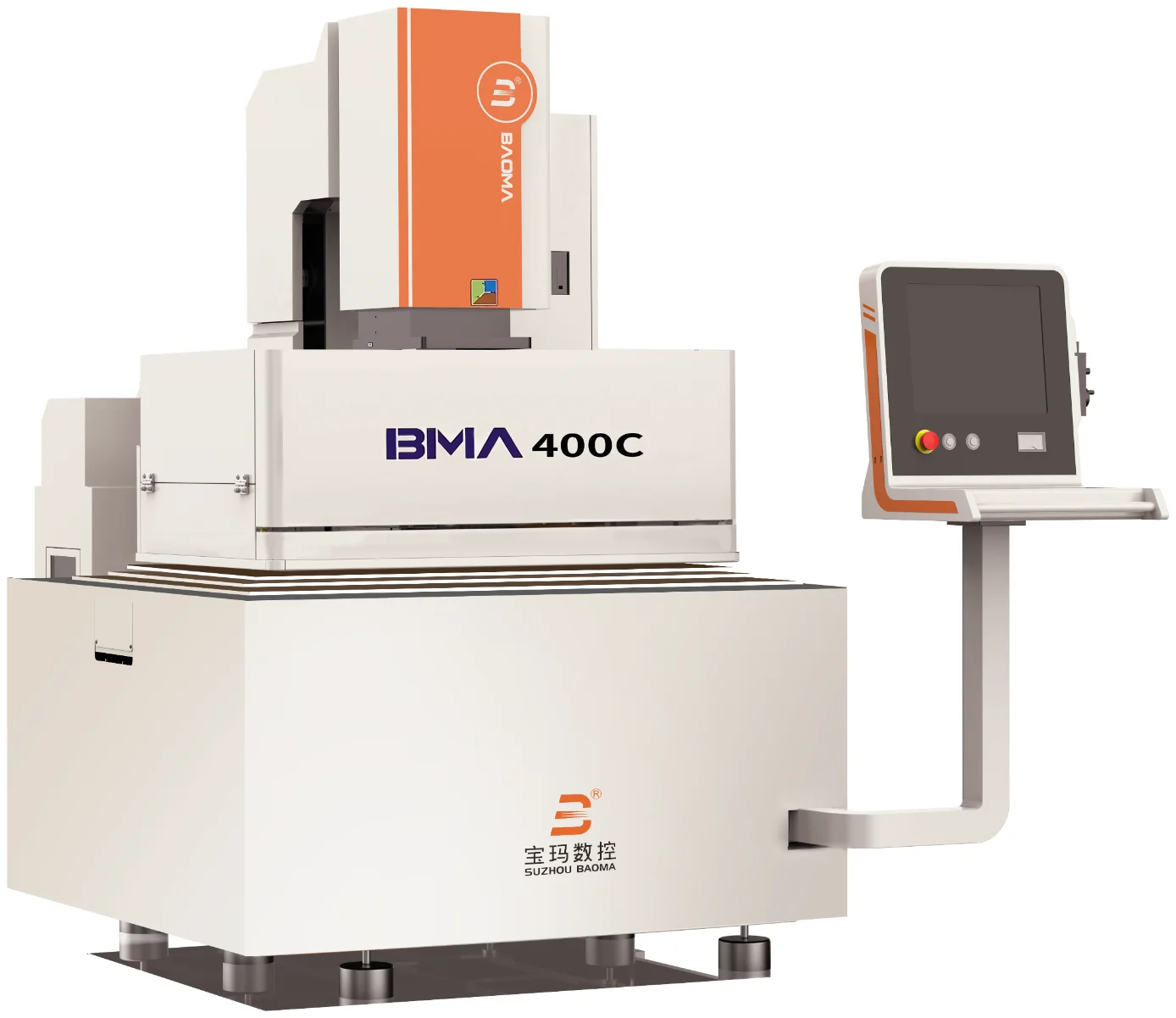
The BMA400C wire EDM record has X/Y travel 400 × 320 mm, a 650 × 420 mm table and 400 kg table load. Its maximum thickness entry is 300 mm, but the ±10° taper entry applies within 100 mm thickness. Combining those two rows into “300 mm thick at ±10°” would create a capability the table does not state.
Place the blank, clamps, wire route and retained slug on one setup drawing. Mark guide clearance and the changing top/bottom outline. A table-load limit does not establish stability after a cut separates material, and an axis travel does not establish tool access along every clamped edge.
The original table separately gives peak cutting-area rate 350 mm²/min, best roughness 0.6 μm and accuracy ≤±0.003 mm. It does not give the shared material, thickness, wire, number of cuts and measurement conditions for one simultaneous result. Aluminium-cutting equipment is listed optional. Use a material-specific trial rather than attaching all three headline figures to the intended part.
3. A second Z stroke does not double the hole depth
The BMD703A-400CNC small-hole record lists X/Y travel 400 × 300 mm and a 510 × 320 mm table. Its Z entry is 300 + (300) mm, with electric secondary-stroke control; the separate machining-depth entry is 0–300 mm. The machine-stroke notation is not a 600 mm drilling-depth claim.
The Ø0.2–3.0 mm entry is electrode clamping range. It is not a guaranteed finished-hole diameter range, aspect ratio or straightness. Specify diameter at entrance and exit, the measurement method, breakthrough condition or blind depth, and access for inspection. The original 50–60 mm/min drilling-rate entry explicitly depends on material and electrode.
Depth control, a probing rod and external spray are listed standard. A filter tank and automatic electrode change are optional. The fourth-axis option field contains a dash; it does not confirm a supplied rotary unit. A useful trial records electrode wear, replacement, flushing interruptions and completed acceptable holes, including positioning and inspection time.
4. Keep ZNC and an orbiting-head option in the cavity specification
The EDM450ZNC die-sinking record names single-axis numerical control. Its source page path contains “CNC”, but its actual title and product designation say ZNC. That path cannot establish programmed X/Y motion, simultaneous three-axis operation or an automatic electrode magazine.
The source table gives X/Y travel 450 × 350 mm, table load 1,000 kg and spindle load 150 kg. Electrode-head-to-table distance is 180–580 mm. Draw the electrode, holder, blank, cavity depth, flushing and withdrawal space together; do not test blank height alone against the head distance.
The ≤0.2 Ra μm best-surface entry explicitly requires an orbiting head. Maximum removal rate 400 mm³/min and minimum electrode consumption ≤0.3% are separate source entries without a common process condition. They do not prove that the deepest corner, finish and low wear can be achieved together in the intended cavity. Measure the released cavity's form, corners, depth and surface after the complete roughing/finishing sequence.
5. Compare accepted parts, not unlike rate units
These sources express wire cutting in mm²/min, hole drilling in mm/min and cavity removal in mm³/min. Those units describe different process outputs. Sorting the three numbers from largest to smallest would not rank machine productivity. Even within one process, a peak figure excludes parts of the production sequence.
For the agreed material and drawing, record setup, threading or electrode preparation, processing, replacement, unloading, cleaning and inspection. Count acceptable parts or features over a stated complete cycle. Record rejected features and why. Keep that trial result separate from the manufacturer's nominal table and from any other material or fixture.
6. Put these items into the enquiry
- Feature: through-profile, small hole or blind cavity; drawing revision and datum scheme.
- Material: conductive material grade, heat-treatment state, blank condition and stock allowance.
- Access: support/clamp drawing, wire threading or electrode approach, withdrawal and flushing routes.
- Finish: dimension and geometry limits, surface requirement, measurement locations and method.
- Build: exact machine/control designation, electrodes or wire, dielectric, filtering, orbiting and replacement options.
- Trial: agreed specimen and complete operation sequence, acceptable output and rejection criteria.
- Installation: electrical supply, lifting and occupied layout, fluid handling, service access and support responsibility.
Review the Baoma process-family profile and the three linked exact-model records before preparing a Baoma RFQ through CNCVerified. Attach the drawing and process question; do not replace them with “EDM machine required”. A complete enquiry makes the unresolved configuration visible before it becomes an installation or acceptance problem.