
Will the fixture fit? Check pallet load, swivel clearance and tools
A blank inside the axis travels is only the beginning. Use two specific GROB configurations to check the mounted assembly before comparing quotes.
A blank can fit a machine's linear travels and still fail the proposed setup. The clamp may hit during a swivel, the pallet configuration may allow less load, or the cutter cannot reach a feature without the holder entering the part. Before comparing quotations, put the complete mounted assembly into the comparison.
This guide uses the GROB G350 milling centre and G350T mill-turn centre as two specific catalogue examples. The GROB China profile explains the company and configuration questions. The figures below were checked against the respective manufacturer pages on 12 October 2026; they are catalogue limits, not approval of your fixture, part or production process.
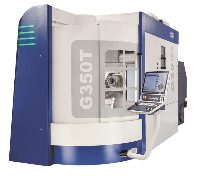
1. Select the pallet configuration before the load limit
| Manufacturer entry | G350 | G350T |
|---|---|---|
| X / Y / Z travel | 600 / 855 / 750 mm | 600 / 855 / 750 mm |
| Table diameter | 570 mm | 570 mm |
| Interference diameter | 720 mm | 620 mm |
| Table load, without pallet | 400 kg | 350 kg |
| Table load, with pallet | 340 kg | 270 kg |
| Single-disc magazine tool length | 365 mm, HSK-A63 | 365 mm, HSK-A/T63 |
The source order differs: G350 prints its loads as without/with pallet, while G350T prints with/without pallet. Copying both pairs in the same order reverses one comparison. The table above deliberately uses separate labelled rows.
List the masses of the blank, fixture body, jaws, clamps, adaptors and any additional mounted equipment. Ask the supplier exactly which components its table-load definition includes and how the pallet is accounted for. Do not subtract pallet mass twice, or assume that a number called “workpiece weight” includes your fixture. A final assessment also needs the permitted centre of gravity, moment and inertia for the selected table and motion; those limits are not established by the load row alone.
For an illustration only, suppose a proposed assembly includes a 230 kg blank and 65 kg of fixture and clamps, giving 295 kg before any further components required by the supplier's definition. That is already above the G350T's listed 270 kg with-pallet limit. Being below G350's 340 kg with-pallet figure would only clear this preliminary mass comparison; it would not establish clearance, retention, dynamics or suitability. These are assumed masses, not a measured customer job.
2. Draw the swept assembly, not just the blank's bounding box
Both examples list the same linear travels and table diameter, but their interference diameters differ by 100 mm. These entries are not interchangeable. Table diameter describes the table; travel describes axis movement; interference diameter is a separate catalogue entry. None by itself guarantees that a rectangular blank with protruding clamps can execute the intended swivel at every tool position.
Send a mounted CAD assembly with the actual offset from the table centre, locating surfaces, support points and every clamp in its closed position. Mark required indexed orientations and simultaneous paths separately. Include loading and unloading positions, probe moves, tool changes, coolant hardware and withdrawal moves, not only the cutting path.
Ask for a configuration-specific collision review using the machine, spindle, holder and fixture geometry that will be supplied. An image of a part inside an enclosure is not that review. If a clamp must move to reach a face, treat the move as a separate setup with its own retention, datum and measurement plan.
3. The holder and magazine position are part of the tool choice
The two pages list a 365 mm single-disc magazine tool-length entry for their respective interfaces. Their double-disc entries are 365 / 180 / 550 mm for bottom / top / over both discs. The 550 mm figure does not apply to every slot. A long assembly can occupy more magazine space and alter the usable tool arrangement.
Prepare the complete tool list: cutter, holder, extensions, gauge length, maximum diameter, mass and sister tools. Ask how length is defined in the selected package, which positions can accept each assembly, and what adjacent-slot restrictions apply. Include the probe and the mill-turn tools where relevant.
A longer tool may help reach below a tall fixture, but it also changes collision clearance and the cutting process. Do not turn nominal reach into a promise of finish, stiffness or cycle time. Trial the difficult feature with the intended holder and overhang, material and stock allowance.
4. Turning capability needs a named route and an approved assembly
G350T lists a 1,200 rpm maximum B-axis speed and a mill-turn table with standard star-shaped T-slots or optional pallet clamping. That maximum is not a safe operating speed for every blank and fixture. Obtain the supplier's permitted operating envelope for the actual rotating mass, balance, retention and selected configuration before running a trial. Do not calculate approval from mass alone.
The G350 page also describes an optional Interpolation turning PLUS software route. It would therefore be misleading to infer “no turning operation of any kind” from the G350 milling-centre label. Equally, that software description does not establish the G350T's table-speed specification or identical turning performance on G350. Identify the feature, control/software package, motion method and acceptance target in the quotation.
Separate milling-spindle speed from workpiece/table rotation. The G350 standard spindle package and G350T's listed HSK-A/T63 spindle are different catalogue choices; speeds and torques from different versions or application examples cannot be combined into one delivered machine.
5. Agree what the mounted-part trial must demonstrate
Use a representative drawing with the hardest relationship between features: an opposite-face datum, deep pocket or a turned bore related to a milled face. Keep the production fixture and intended tool lengths. If pallet exchange is part of the purchase, include repeat loading, cleaning, seating checks and identification in the trial.
Agree measurement method, temperatures, sample size and whether acceptance is measured clamped or after release. Published machine positioning figures are not finished-part tolerances. Inspect the feature after the full proposed machining and clamping sequence, rather than accepting only a probe reading made inside the machine.
Record setup, loading, machining, tool changes, cleaning, measurement and accepted output. Keep that result separate from a catalogue chip-to-chip figure. A trial that omits the second fixture position or measures a different material cannot establish your complete production route.
6. Send one package that both quotation teams can use
- Part: drawing revision, material, blank dimensions, stock allowance and critical datum relationships.
- Assembly: mounted CAD, component masses, centre-of-gravity information, clamps, pallet and locating scheme.
- Motion: indexed and simultaneous orientations, any turning route, loading and withdrawal positions.
- Tools: complete holder/cutter assemblies, probe, sister tools and proposed magazine arrangement.
- Machine: exact model, spindle, table/pallet, control, software and automation package; manufacturing origin and contractual supplier to confirm.
- Acceptance: representative trial, retained/released measurement condition, agreed inspection method and complete accepted-part sequence.
Compare the G350 record with the G350T record, then send the actual setup through the CNCVerified GROB RFQ. If fixture mass, clamping geometry or the turning route is still missing, ask for those inputs first; a catalogue comparison cannot supply them.