

China Tsugami · Pinghu, Zhejiang
Automatic lathes & machining equipment
Tsugami: plan the part and the grip.
Compare 20 mm angled work with four 38 mm tooling routes. Review the grip, transfer and released part.
Find your machining route ↓Tsugami RFQ ↗
Original model material and 2025–2026 issuer report · reviewed 8 October 2026
Start with diameter, feature direction and the second grip.
China Tsugami publishes automatic lathes alongside turret machines, machining centres, grinding and thread/form rolling equipment. The five automatic-lathe references below span different workholding and tool arrangements. The first decision is whether the drawing needs angled live-tool features, a short-part collet arrangement, overlapping turret operations or a larger milling-tool package. Nominal diameter alone cannot answer that.
| Drawing/process question | Model reference | Published arrangement | Check before choosing |
|---|---|---|---|
| Angled features within a 20 mm reference | SS207 | B-axis live tools; 35 tools; main/back 200–10000 rpm | Actual tool angle, reach and main/back collision clearance; rotary guide bushing is optional |
| 38 mm turning with rear machining | B0385-III | 31 tools; main 6000 / back 7000 rpm | Rear rotary tools and off-centre attachment are options; specify the offered package |
| Short 38 mm-class workpieces and bar use | B0385L-III | Adjustable collet for short workpieces; 31 tools | Bar condition, gripping length and remnant on your part; do not infer long stroke from “L” |
| Several front/back operations to overlap | B038T | Three paths; 8-station turret; 45 total tools | Allocate tools and synchronisation on a real programme; 45 tools is not 45 turret stations |
| Complex bar work with more milling tools | B038M | CAPTO C4; tool spindle up to 20000 rpm; 40-tool magazine / 52 total tools | Holder assemblies, cutting-load curve, tool-change clearance and released-part tolerances |
Swipe to the final column on a phone. Diameter entries are maximum machinable diameter references, not proof that every bar stock, feeder, guide or part length is compatible. Confirm the build and process with the drawing.
SS207: locate the angled hole in the complete tool zone.
The SS207 page describes B-axis live tools indexed by the NC programme and simultaneous four-axis machining with CAD/CAM. It does not describe that operation as simultaneous five-axis machining. Back-tool-post Y motion can support concurrent main/back work, but the actual holders, reach and collision envelope decide which operations can run together.
The reference diameter is 20 mm, with main and back spindles each listed at 200–10000 rpm and 35 tools. Rapid motion is 32 m/min except X1/Y1 at 24 and Y2 at 15. Those are motion limits, not a cycle-time result. For an angled drilling or milling feature, send the angle, depth, access direction and neighbouring shoulders; request the proposed tool and programme simulation.
The direct-drive rotary guide bushing is explicitly an option. Agree the guide/support arrangement, bar tolerance and straightness, feeder and part length rather than treating an optional mechanism as the base build. The published 2.2/3.7 kW pair has no duty labels in the reviewed table; obtain the offered motor curve and rating conditions.
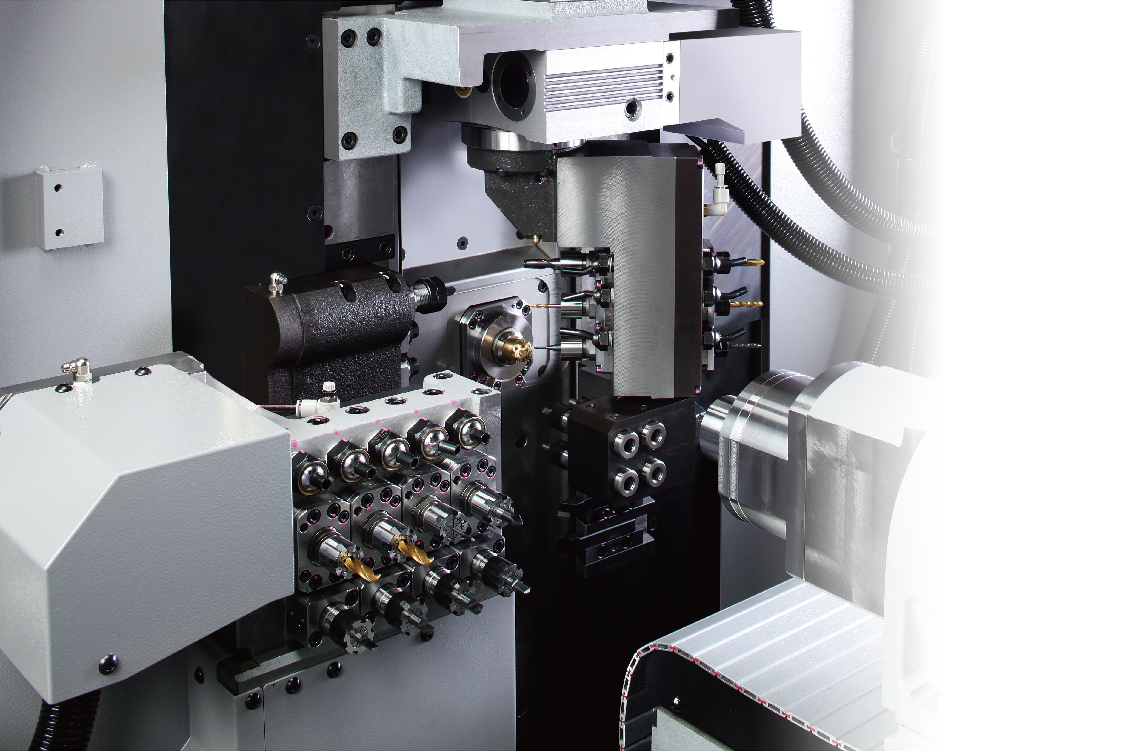
B0385-III and B0385L-III: similar headline figures, different gripping questions.
Both references list 38 mm maximum machinable diameter, 31 tools, 6000 rpm main and 7000 rpm back spindle, with a 2770 × 1515 × 2050 mm body and 4850 kg mass. Those shared figures do not make their workholding descriptions interchangeable.
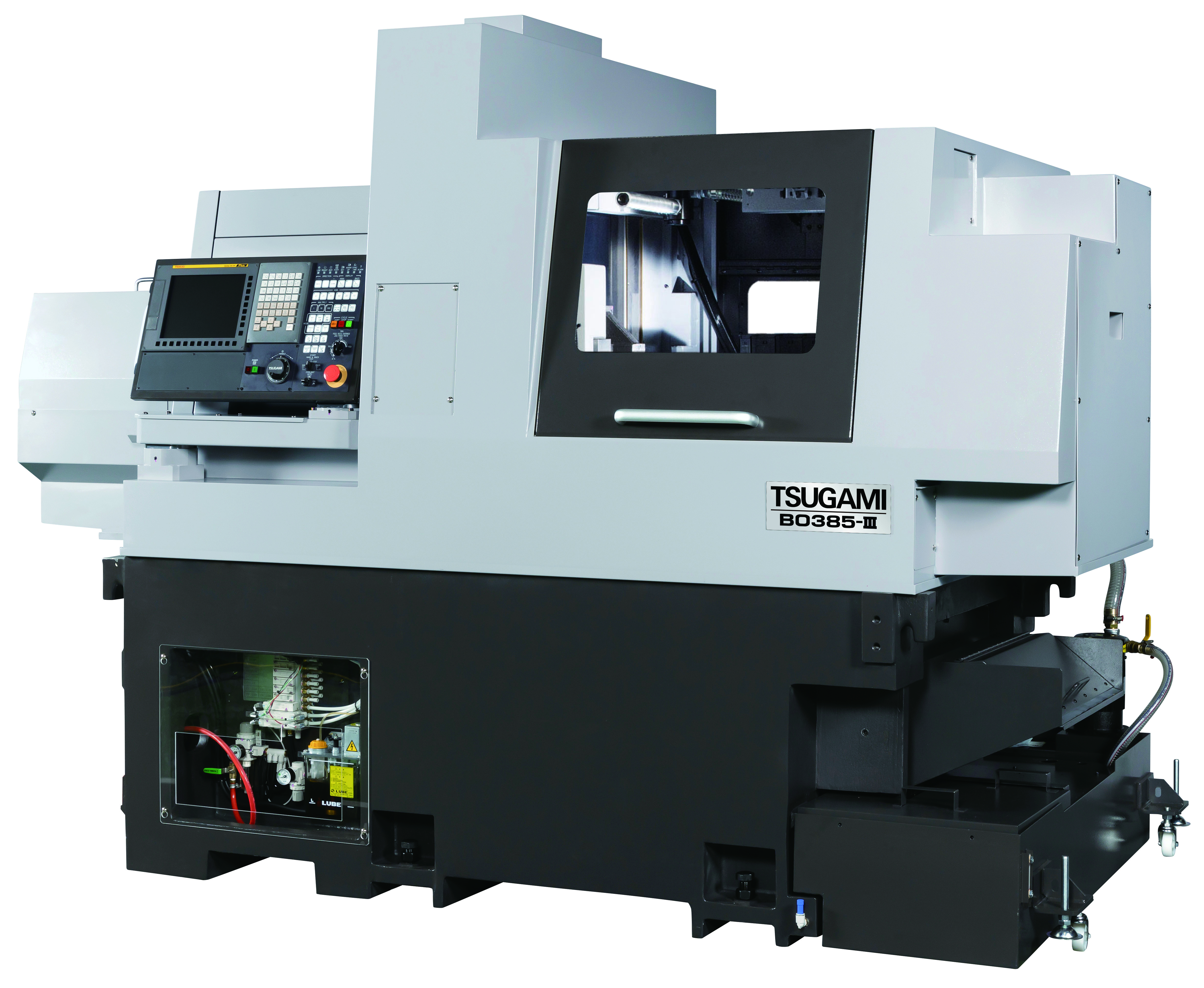
B0385-III: specify rear-tool access.
The manufacturer describes a “Double Spindle” arrangement and a wide tooling zone. Rear rotary tools are optional, and off-centre machining calls for an attachment. Send rear-face features and their datum relationship to the front operation; ask which holder, attachment and gripping sequence the quotation includes. A general main/back spindle description is not proof that every rear feature is covered.
B0385L-III: prove the short-part collet plan.
The L model is described with an adjustable collet for short workpieces and reduced remnant length, including a statement that large-diameter ground stock is not required for that arrangement. Make the supplier define acceptable bar condition, unsupported length, gripping allowance and measured remnant for your material. It is not a guarantee for arbitrary stock, and the suffix does not provide a numerical Z stroke or maximum finished-part length.
Each table lists main motor 7.5/11 kW and back motor 3.7/5.5 kW without the rating durations. Confirm the applicable duty, torque curve and offered spindle package; do not treat the larger number as continuously available cutting power.
B038T or B038M: choose the tooling architecture, not the larger tool count.
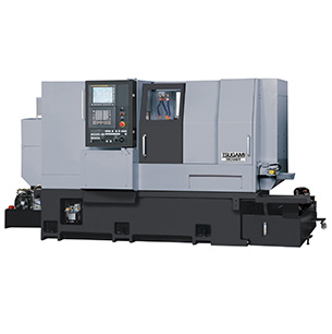
B038T — allocate three paths.
The eight-station turret can carry multiple tools per station, using Y selection for the described changes without turret indexing. Back-tool-post Y motion and live tools permit milling arrangements. The published total is 45 tools, not 45 turret stations. Build a holder map and main/back path timing chart with synchronisation and clearance checks.
Main speed is 200–5000 rpm and back speed 200–7000 rpm. Listed X1/X2/X3, Y1/Y2/Y3 and Z1/Z2/Z3 rapid motion is 24 m/min; that list is not a nine-axis simultaneous-machining statement. Three control paths create opportunities to overlap operations, but transfer waits, cutting imbalance and shared clearance can still govern the cycle.
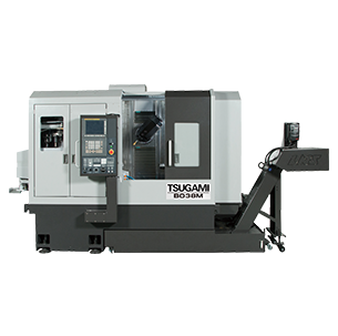
B038M — plan milling assemblies.
The B038M description specifies a tool spindle up to 20000 rpm and dual-contact CAPTO C4 holders. That tool-spindle speed is separate from main/back turning spindle speeds of 200–7000 rpm. The 40-tool magazine and 52 total tools are separate counts. Request the usable pocket map for your assemblies, probes and sister tools.
Check holder reach, cutter mass/diameter, tool-change clearance and the milling spindle’s torque/duty curve. The main and back motor entries are each published as 5.5/3.7 kW, with no duty labels; do not reverse their order or import B038T’s motor pair. Complete machining from bar remains a process proposal until the transfer and released sample meet the drawing.
Make the second grip and part release part of acceptance.
1. Prepare the bar and first datum
Specify material, diameter tolerance, straightness, blank/bar length, feature sequence and support needs. Review collets, guide or guide-free arrangement, feeder interface, chip/coolant compatibility and the practical bar-end allowance. A nominal diameter ceiling does not establish the complete supply chain for a long or slender part.
2. Transfer without losing the datum
Mark which surface the back spindle grips and the minimum engagement after front machining. Ask for synchronisation, pull-out and cutoff sequence, jaw/collet marks, supported length and collision simulation. Allocate angled live tools, turret paths or milling assemblies to the actual model; do not combine the five catalogues into one machine.
3. Measure the finished, released part
Agree a sample programme on the quoted control and tooling. Inspect front-to-back concentricity, shoulder relationship, angled-feature location, burrs and any thin-wall distortion after release. Record cutting, transfer, measurement, loading and tool-life interventions separately. Include safe restart after a controlled stop and the procedure for a worn or broken tool.
Ask for serial-machine test records and agreed sample inspection. The reviewed pages do not supply your fixture-specific accuracy, maximum finished-part length or accepted production cycle; those belong in the quotation and trial result.
Confirm the operating factory and train on the purchased configuration.
The official China profile places its headquarters and plant in Pinghu, Zhejiang. The issuer’s 2025–2026 report separately identifies the listed company as an investment holding company and its Zhejiang subsidiary as a manufacturer and seller of high-precision CNC machine tools. The report records that subsidiary’s registration in September 2003 and also identifies an Anhui manufacturing subsidiary. This dated group relationship does not determine where every serial machine is built or independently certify a machine.
Obtain the selling, manufacturing and servicing entities, production location and exact model revision for the offered serial number. Confirm the control, feeder, bar support, live-tool holders, coolant, unloading arrangement, installation drawing and included safety equipment. Catalogue body dimensions leave additional feeder, conveyor, door and service access to the delivered layout.
The published technical-support process offers basic, practical and customer-specific training, with requested objectives discussed before the agenda is confirmed. Use that process to request training on your paths, guide/collet setup, tool offsets, transfer, inspection and restart. Agree destination commissioning, programme/parameter backups, warranty responsibility and spindle/live-tool spares; neither a branch list nor group membership establishes a local response time.
Send the drawing and the gripping sequence.
Include material and bar condition, complete geometry, angled/rear features, critical front-to-back datums, released tolerances, batch mix and target cycle. Add proposed collet/guide arrangement, feeder, tool assemblies, transfer engagement, coolant and installation country/utilities.
Ask for an itemised model/configuration proposal, holder/path layout, supported part length, sample programme and inspection plan through CNCVerified.
Prepare a Tsugami RFQ ↗