
Gfir turning
Gfir GC6-E
Zhejiang Gfir Technology and Industrial Co., Ltd. · Hangzhou
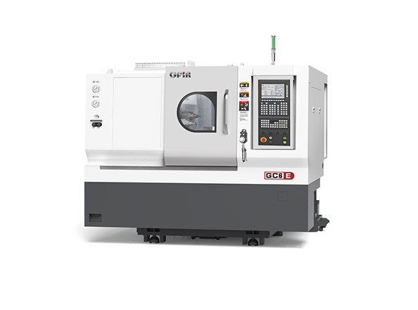
- Main/sub workholdingCL42 / CL30
- Bed swingØ300 mm
- Maximum turning diameterØ120 mm (disc work)
- Maximum machining length160 mm
- Bar capacityØ42 mm
GC6-E is recorded with CL42/CL30 main/sub workholding, Ø300 mm bed swing, Ø120 mm disc turning, 160 mm maximum machining length and Ø42 mm bar passage. Bed swing and disc turning have different meanings. Its X1/X2 travel is 145/360 mm and Z1/Z2 is 260/230 mm; the compact work-length entry should not be replaced with a GC6-C value.
The original description lists upper Y as optional. The tooling table likewise marks the upper 12T/70 driven turret as optional, and names lower gang-tool, servo-turret and driven-turret alternatives separately. That list describes alternatives rather than one machine containing all arrangements. The original lower gang-tool line mentions five stations.
Main/sub speed limits are 5,000/6,000 rpm, configuration-dependent, with Ø56/Ø42 mm bores. X and Z unidirectional repeat positioning are 0.004 and 0.005 mm, and external dimensions are 2,250 × 2,100 × 1,945 mm. Repeat positioning is axis data, not a measured component result. Factory-specific transaction services remain unavailable for this technical reference.