
5-axis · Neway
Neway VM450F
Neway CNC Equipment (Suzhou) Co., Ltd.
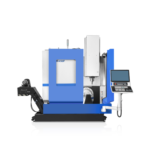
Whole original image marked VM450F; no numerical or supplied-controller guarantee inferred.
Neway names VM450F as an X/Y/Z/B/C five-axis simultaneous configuration. Its exact column gives a Ø450 mm table, 200 kg maximum table load and 450/400/400 mm linear travels. Count the fixture, jaws, clamps and blank together, then supply the loaded centre of gravity. A compact impeller, housing or multi-face component still needs its actual swept envelope and tool access checked against this build; the table diameter alone does not approve the part.
B/C rotation is listed as ±110°/360°, with a 140–540 mm spindle-nose-to-table distance. Draw the complete holder, tool, fixture and workpiece at the difficult B angles, including entry and withdrawal. Ask how permitted load and moment change with orientation. The listed axis limits do not establish collision-free motion through a full circle or an unrestricted tool reach at maximum tilt.
The VM450F table lists a 15,000 rpm maximum spindle speed, a 10.6 kW main-motor entry, No.40 7:24 taper and MAS403 BT40 holders. It gives a thirty-position disc magazine. The motor entry has no duty duration in this table, so obtain the spindle torque-speed curve and the intended sustained-cut rating rather than treating the number as a finished-part capability.
The reviewed table does not give complete tool diameter, length, mass or occupied-neighbour allowances. Submit the assembled tools and ask for a populated magazine schedule and clearance check. Do not import the tool limits from a three-axis VM table or the neighboring FA version. Confirm probing, coolant, rotary calibration and the exact controller functions in the same quotation.
Provide the required surfaces, datums and tolerance zones together with the CAM fixture/tool model. Run the intended postprocessed B/C program through its most restrictive orientations, then inspect the released part under agreed thermal and measurement conditions. Record witness marks, accessibility and any manual repositioning; nominal simultaneous-axis capability is not a demonstrated surface result.
Agree the rotary-centre calibration, controlled restart after a stopped cycle, tool setting, maintenance access and destination training. Time loading, cutting, tool changes, probing and inspection separately. The published 48/48/40 m/min linear rapids describe traverse motion, not a production rate or proof that all five axes can follow a particular cutting path at those speeds.
Catalog specifications
- Motion described
- X / Y / Z / B / C simultaneous
- Table diameter / maximum table load
- Ø450 mm / 200 kg; fixture and angular loading conditions to confirm
- X / Y / Z travel
- 450 / 400 / 400 mm
- B / C rotation reference
- ±110° / 360°
- Spindle nose to table
- 140–540 mm
- Maximum spindle speed
- 15000 rpm