
5-axis · Neway
Neway VM650F
Neway CNC Equipment (Suzhou) Co., Ltd.
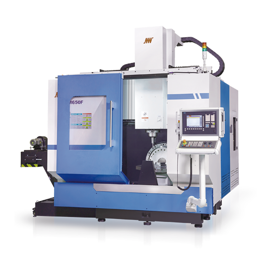
Whole original image marked VM650F; no numerical or supplied-controller guarantee inferred.
VM650F is described with X/Y/Z/B/C simultaneous motion, a Ø650 mm table and 300 kg maximum table load. Its exact linear-travel column is 650/550/500 mm. Include the blank, fixture and clamps in the mounted mass, and specify the centre-of-gravity offset. A large circular table does not establish the allowed part height or loading moment while tilted.
The B/C reference is ±110°/360°, and spindle-nose-to-table distance is 175–675 mm. Check the shortest tool’s reach and the longest holder’s approach at the required B angles, with the actual fixtures and enclosure. Request the permissible angular loading and the complete collision model. A neighboring model’s larger Y travel or different rotary label is not an extension of VM650F.
The reviewed F column identifies HSK-A63 for both spindle interface and holders, an 18,000 rpm maximum spindle speed, a 15.5 kW main-motor entry and a thirty-position disc magazine. Preserve that single configuration in the quotation, tool list and CAM model. Do not turn it into the No.40/BT40, twenty-four-tool FA package because the model names share “650”.
Ask for the actual spindle torque-speed and duty curves, permitted tool mass/length/diameter, balance requirements and adjacent-slot occupancy. The table does not define those tool limits or a power duty duration. Check the delivered holder/retention system and each assembled tool, including probes and large heads, before treating magazine count as the usable production tool set.
Choose a representative component and identify the surfaces whose quality depends on continuous rotary motion. Demonstrate the intended controller functions and postprocessor, rotary-centre calibration, holder/fixture clearance and safe restart. Compare released-part geometry and surface continuity at the difficult orientations, not just a machine-motion demonstration without cutting.
Keep setup, tool changes, chip removal, measurement and manual intervention in the elapsed trial. Linear rapids are listed as 48/48/40 m/min; those values neither establish a cutting feed nor a delivered cycle time. Confirm utilities, service access, parameter/software backups and the destination commissioning responsibility separately from the machine-body photograph.
Catalog specifications
- Motion described
- X / Y / Z / B / C simultaneous
- Table diameter / maximum table load
- Ø650 mm / 300 kg; angular loading conditions to confirm
- X / Y / Z travel
- 650 / 550 / 500 mm
- B / C rotation reference
- ±110° / 360°
- Spindle nose to table
- 175–675 mm
- Maximum spindle speed
- 18000 rpm