

北京北一机床有限责任公司 · Beijing, China
BYJC: choose the machining route, then the manufacturing entity.
A valve body, a large five-face housing and a slender turbine blade need different machines. Compare the reviewed MXR, Aμ and XKH routes, including the joint venture behind each series.
Find your process ↓Prepare a BYJC RFQ ↗
Manufacturer’s company and series materials, plus Beijing’s 26 November 2025 entity record, reviewed 8 October 2026
Three workpiece routes, three different checks
Small or medium box and valve bodies
Start with the BYJC–OKUMA MXR vertical centres. Check the feature coordinates and fixture height, then choose between BT40 and BT50. An optional rotary table adds a different setup; it does not turn the standard machine into a simultaneous five-axis blade centre.
Large housings with several machined faces
Start with the Aμ gantry reference. Review attachment-head reach, indexed orientation and the datum transfer between faces. Five-face machining describes access to faces; it does not establish continuous five-axis contouring.
Turbine blades or narrow curved profiles
Start with the BYJC–Ferrari XKH series. Draw the actual root/tip fixture, support and rotary sweep. Linear travel and an undefined U-axis figure are not a guaranteed finished-blade length.
The group also lists heavy turning, other machining centres, grinders, special machines, production integration and remanufacturing. Those wider ranges require their own model and build review. This comparison covers the five linked records below, rather than treating the entire group catalogue as one machine supplier configuration.
MXR: a larger table also changes the spindle interface
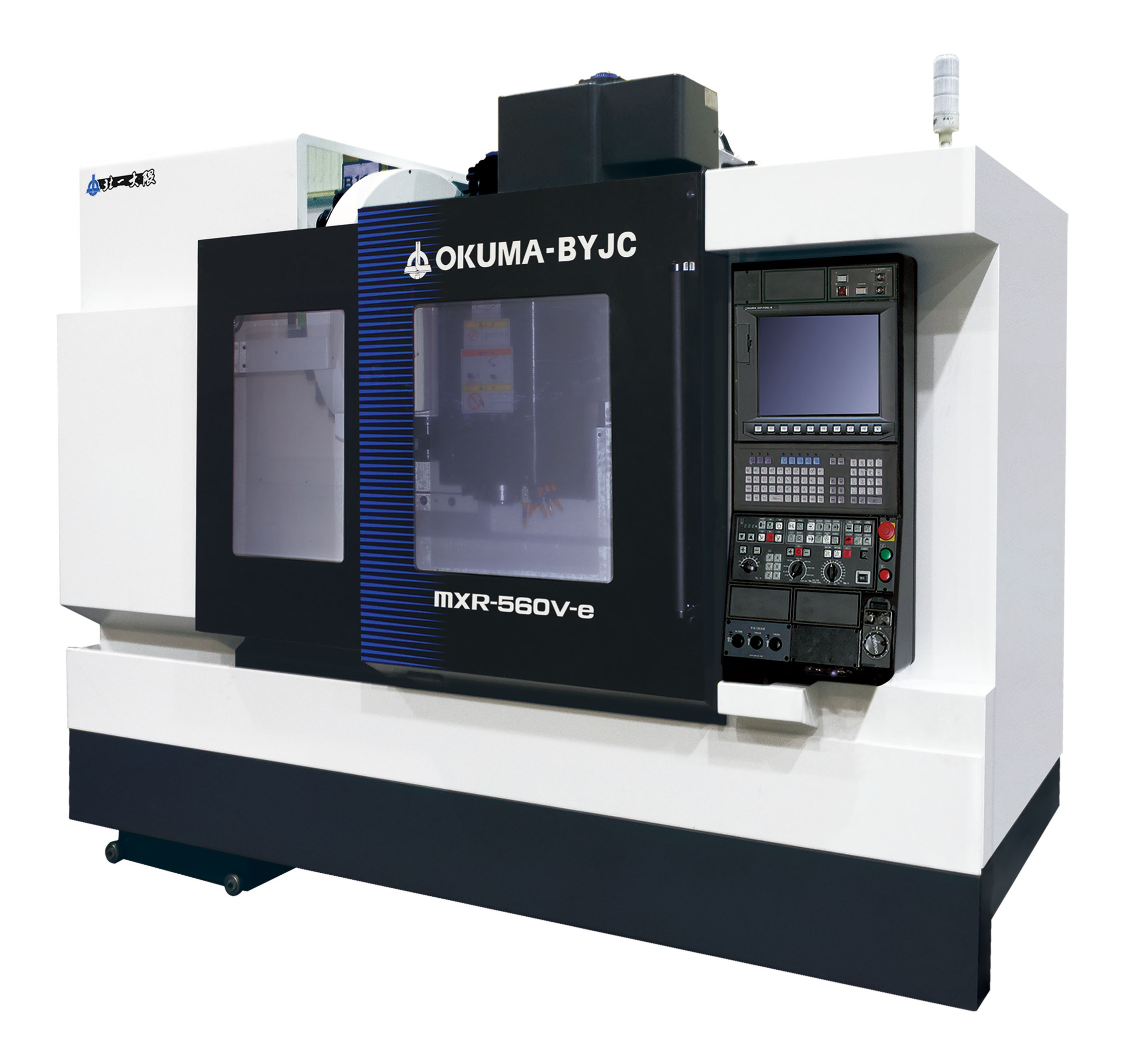
The manufacturer places MXR-V-e in the BYJC–OKUMA range for milling, drilling, boring and tapping small/medium box parts and valve bodies. The two reviewed columns share 450 mm Z travel and a 20-position magazine, but not the same spindle or continuous power.
A wider fixture may justify the 560V-e; a process based on existing BT40 tooling may point toward the 460V-e. Compare the complete tool assemblies and sustained cutting duty before using table size as the only selection rule.
On a phone, swipe the table. Table dimensions retain the manufacturer’s printed order; obtain the layout drawing before assigning each dimension to an axis.
| Reference | MXR-460V-e ↗ | MXR-560V-e ↗ |
|---|---|---|
| X / Y / Z travel | 762 / 460 / 450 mm | 1050 / 560 / 450 mm |
| Printed table dimensions | 460 × 1000 mm | 1300 × 560 mm |
| Maximum table load | 500 kg | 700 kg |
| Tool interface | BT40 | BT50 |
| Spindle range | 50–8000 rpm | 50–6000 rpm |
| 10-minute / continuous power | 11 / 7.5 kW | 15 / 11 kW |
| Tool positions | 20 | 20 |
The source heads its table “width × length” but prints the two models’ dimensions in different apparent orientations. Use the table drawing, T-slots, fixture coordinates and actual tool approach to resolve that. The 1300 mm table dimension does not establish 1300 mm X travel.
Include the part, fixture and any rotary table in the mass and clearance check. Both models have 450 mm Z travel, but the reviewed table does not state the spindle-nose window. Request the minimum/maximum nose distance, holder projection and rotary centre height. For long boring tools, check withdrawal above clamps and chips as well as the deepest cut.
The optional CNC rotary table is described as four axes with three simultaneous movements. Specify whether you need indexing, coordinated machining or a different five-axis platform. Agree rotary load, clamping, control integration and collision review separately. Time drilling/tapping, tool changes, handling and chip clearing on the actual valve or housing; spindle rpm alone does not determine output.
Turn the MXR selection into a quoted configuration
Before comparing a supplier’s price, mark the exact model, controller revision, spindle drive and duty, magazine and complete tooling in one configuration schedule. Add the fixture, loaded mass, the lowest and farthest feature and the longest holder. Use the milling selection notes to check travel, spindle-nose clearance and the delivered scope against that setup.
If the quotation adds a rotary table, attach the proposed part program and state which movements occur during the cut. The fourth-axis selection notes distinguish indexing from coordinated rotary cutting and a swivelling head. A related process category does not prove that an MXR quotation includes those functions, rotary hardware, licenses or a validated postprocessor.
Request a marked-up build drawing and a trial plan that identifies the manufacturing and commissioning responsibilities already discussed below. Keep the controller/software list, workholding review and released-part measurements with the accepted configuration. A group catalog title or an optional-axis description is not acceptance evidence for the delivered unit.
Aμ gantry: head access comes before a five-face promise
The page headed XKAμ ↗ describes XHAμ in its text and labels its specification table Aμ. Keep those designations visible in the quotation until the manufacturer identifies the exact build and drawing. The reviewed table gives 5000 / 2500 / 1500 mm X/Y/Z travel and 2000 mm table width; it does not establish table length or load.
The manufacturer describes hydrostatic guides, a wrapped hydrostatic ram and a C-axis indexing/locating unit that clamps different milling heads. That is evidence for the described attachment-head approach to five-face machining, not proof of simultaneous five-axis capability.
- Mechanical spindle head reference
- 4000 rpm maximum; 37 kW S1; 1000 Nm S1
- Published rapid rates
- X/Y 20 m/min; Z 15 m/min, converted from the table’s mm/min
- What changes with another head?
- Reach, tool centre, usable envelope, orientation, cutting ratings and head-change sequence
Ask for the head-specific speed/torque curve; maximum rpm and maximum torque are not a promise that both occur together. Supply the largest housing with all clamps and the farthest side bore. Review spindle reach with the selected head, ram extension, clearance at the crossrail and the full approach/retract sequence.
For a datum shared by several faces, agree head seating and indexing checks, tool-centre calibration, probing and thermal conditions. Cut and measure the actual face-to-face relationship after all required orientations. Include head changes in the timed trial, and specify hydraulic supply, foundation, service access and installation inspection. The table’s S1 ratings cannot replace a finished-part acceptance report.
XKH: build the fixture around the root, tip and rotary sweep
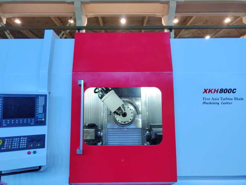
The manufacturer attributes XKH to BYJC–Ferrari and describes simultaneous five-axis machining of turbine/gas-turbine/aircraft-engine blades and other narrow profiles, with steel, stainless steel, superalloy and titanium applications. These are stated applications, not evidence of aerospace approval or a named customer qualification.
| Reference | XKH400A ↗ | XKH800C ↗ |
|---|---|---|
| X / Y / Z travel | 500 / 300 / 400 mm | 1350 / 400 / 500 mm |
| Published U-axis travel | 400 mm | 750 mm |
| Spindle interface / power | HSK-A63 / 30 kW | HSK-A63 / 30 kW |
| Published torque | 29.1 Nm; duty unspecified | 94.9 Nm; duty unspecified |
| Body L × W × H | 3120 × 2452 × 2412 mm | 3650 × 2880 × 2900 mm |
| Net mass | 8000 kg | 14000 kg |
U-axis travel is not defined as blade length or support spacing in the reviewed table. Request the axis diagram, clamping/support adjustment, permitted part mass, rotary limits and the collision envelope with complete holders. The rapid row prints 30 and 20 under mm/min without a clear explanation; it is excluded from this performance comparison until a model-specific unit is confirmed. Spindle speed and power/torque duty likewise need the selected build sheet.
Locate the blade without distorting it
Supply the root datum, tip support, blank allowance, material/condition and the thinnest section. Agree clamping force, support access and the datum transfer if roughing and finishing use different fixtures. Ask how long, slender sections are supported while the cutter changes orientation.
Prove the toolpath and the released profile
Use the proposed control, postprocessor, cutter/holder and fixture model to check collisions at root fillets, leading/trailing edges and extreme angles. Inspect profile and thickness after release under agreed thermal and measuring conditions. Surface appearance in a photograph is not measured form accuracy.
Repeat the production sequence
Agree tool-life checks, offsets, chip/coolant handling, loading and inspection cadence. Time an accepted blade through the complete sequence. Record how the machine recovers from a stopped cycle and whether re-seating maintains the datum. Include installation and support equipment in the floor plan, beyond the body dimensions above.
Put the manufacturing and service responsibilities in writing
BYJC’s current company page identifies 北京北一机床有限责任公司, headquartered in Shunyi, Beijing. It lists German Waldrich Coburg and Italian C.B. Ferrari within the group, BYJC–OKUMA as a joint venture established in July 2002, and Beijing BYJC–Ferrari for domestic manufacturing/service and Italian-machine sales. A common group name does not establish one manufacturing site or the same standard equipment for every series.
The Beijing public-resource platform’s 26 November 2025 entity record names 北京北一机床有限责任公司 and identifies Shunyi as its administrative area, with data from the Beijing Equity Exchange system. This is a dated entity cross-check, not an independent factory audit, a machine certificate or a current credit guarantee.
Ask the quotation to identify the contracting entity, manufacturing factory, model/revision, serial-unit origin and responsible installer/service provider. Separate machine, attachment heads or fixtures, CAM/postprocessor, probing, training and destination support in the scope. For an MXR rotary package, Aμ head set or XKH blade fixture, define which party proves the integrated process and which measured result is accepted before shipment and after installation.
Send the workpiece route with your drawing
Include the manufacturing route and required faces/profile, material and condition, complete blank/fixture dimensions and mass, datum/clamping/support scheme, tools and spindle duty, selected head/rotary or blade setup, control/CAM/postprocessor, measured acceptance characteristics, batch/changeover target, installation utilities and destination. Ask for the exact manufacturing entity and delivered configuration in the same quotation.
BYJC RFQ ↗